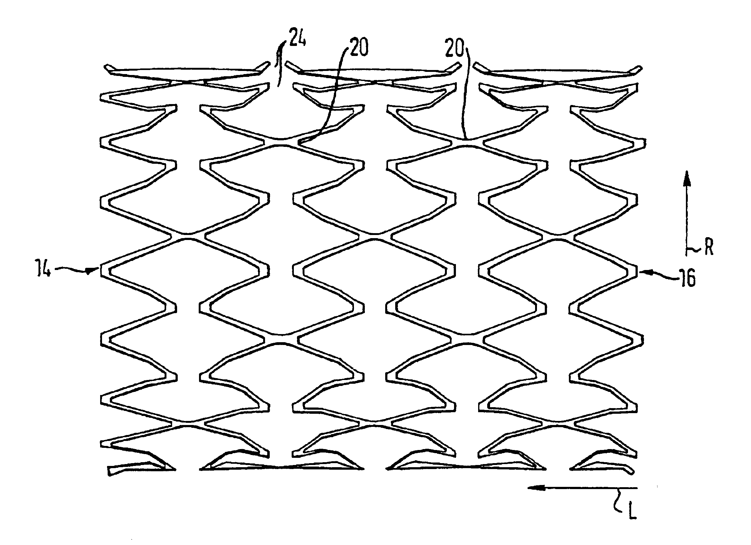
[0008]Thus, an expandable stent in accordance with the invention comprises an elastic tubular lattice structure which has a first end zone, a second end zone, a longitudinal direction and a radial direction. This lattice structure defines an outer
diameter and an inner lumen. It is formed by wall segments, these wall segments branching off at intersections. In addition, the lattice structure is interrupted in at least some of these intersections, whereby the flexibility of the stent is increased. The expandable stent in accordance with the invention is characterized in that at least at the interrupted intersections, the wall segments are expanded in the radial direction of the stent. Consequently, this expansion is directed towards the
vascular tissue which surrounds the stent, the interrupted intersections being located between the first end zone and the second end zone of the lattice structure. The expansion in the radial direction has the effect that even in the case of extreme curvature of the stent along the longitudinal direction, the inner lumen of the vessel is not reduced because the wall segments project into the inner lumen at the interrupted intersections. The solution in accordance with the invention provides a plurality of advantages. Thus it is possible on the one hand to expand and thereby to
implant the inventive stent by means of a
balloon catheter, irrespective of the curvature of the location in the body which is to be treated, or to treat with
balloon catheters the
vascular tissue at that location where stents have already been implanted, and on the other hand to design the stent as a self-expanding stent. In addition, a local reduction of the inner lumen could lead to uncontrollable vascular
system vortices in the liquid which flows through the stent and thereby could lead to new
occlusion reactions. This is also prevented by the solution in accordance with the invention. At the same time, due to the expansion of the wall segments in the radial direction of the stent at the interrupted intersections, the anchorage of the stent in the surrounding
vascular tissue is improved, so that the stent cannot change its position, after it has been implanted. It will be understood that depending on the production process which is selected for the stent, the wall segments can also be expanded at the uninterrupted intersections.
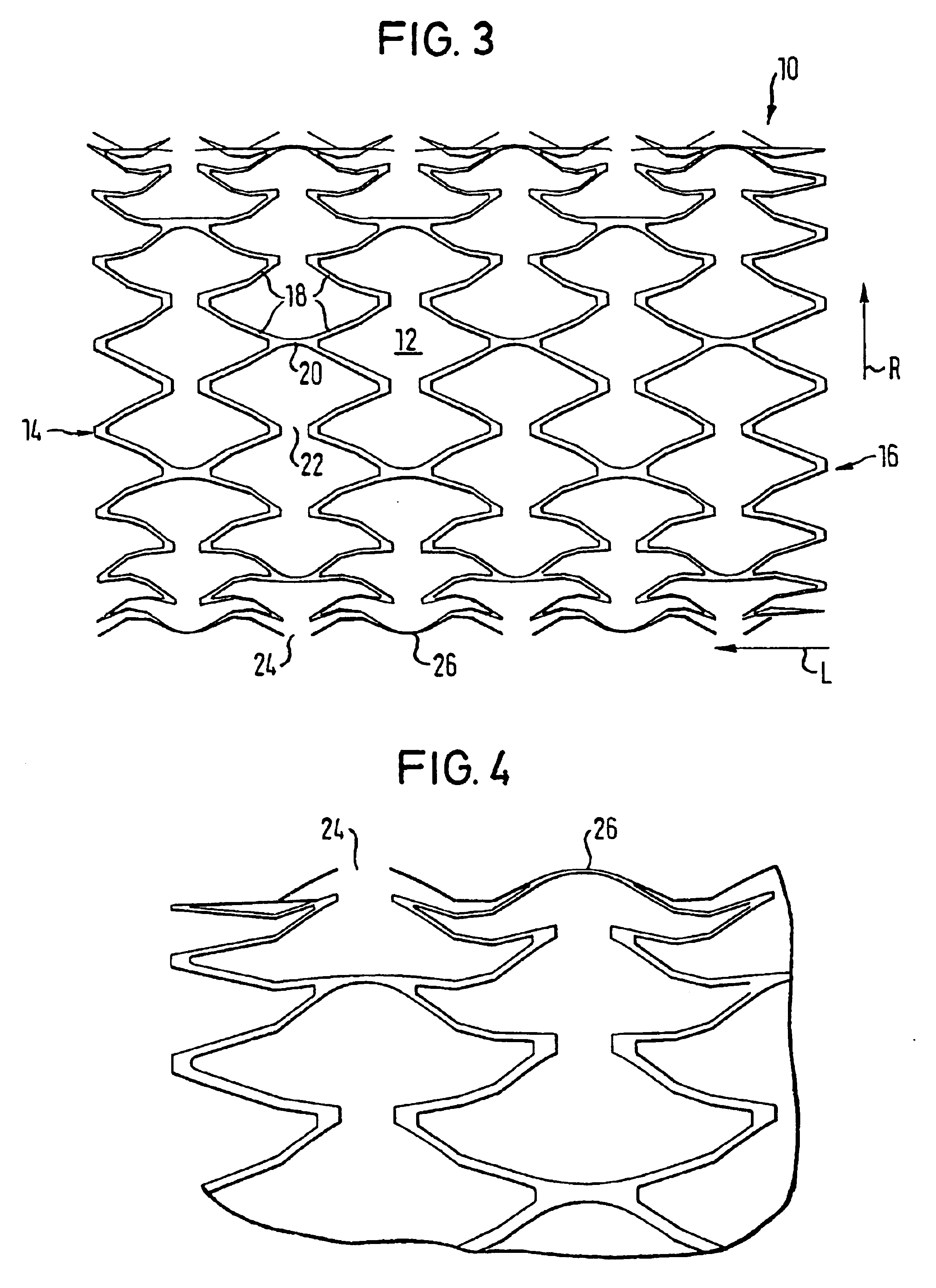
[0010]Advantageously the stent is further developed such that the wall segments are interrupted in
regular distribution over the stent, substantially at two thirds of all the intersections. This distribution is regular both in the
peripheral direction as well as in the axial direction of the stent and the exact pattern of the distribution depends on the form which was selected for the lattice structure. It has been found that an interruption of substantially two thirds of all the intersections is a good compromise between high strength for the stent on the one hand and good flexibility and stability upon deformation of the stent on the other. The flexibility which is thus achieved can also be altered as desired depending on the medical indication, by having a correspondingly different number of intersections be interrupted.
[0011]As was mentioned above, the lattice structure has apertures. In the case of collateral arterial branches, so as to improve the guarantee of further regional supply of the vessels until a re-growth of intima takes place, these apertures advantageously have in the expanded state of the stent an aperture width of maximally 9 mm.
[0013]In order to further develop with advantages the favorable properties of a no-profile stent or of a low-profile stent, the lattice structure in the radial direction has substantially a wall thickness of between 0.2 mm and 0.3 mm. Because this wall thickness may slightly fluctuate in the course of the longitudinal direction of the stent, depending on the production process, the information above is understood as a characteristic wall thickness. In accordance with another advantageous design of the stent in accordance with the invention, it consists of a metallic material which has shape memory. For further
advantage, this material with its shape
memory effect consists of a
nickel-
titanium alloy. The
alloy moieties, which are especially advantageous in accordance with a preferred range of the
alloy moieties, make it possible to design the stent to react to temperature so that it can be inserted into the body in the non-expanded state, expands due to the body temperature when positioned to the required extent and is independently implanted at the position which it is desired to treat.

