Solid electrolytic capacitor and method of manufacturing the same

a technology of electrolytic capacitors and solid electrolytic capacitors, which is applied in the direction of electrolytic capacitors, liquid electrolytic capacitors, variable capacitors, etc., can solve the problems of increasing the demand for improving, not meeting the demand for thin-type elements, and it is difficult to achieve mold package sizes, etc., to achieve low esr, high frequency domain, and large capacity

Active Publication Date: 2005-06-28
TOKIN CORP
View PDF7 Cites 53 Cited by
  • Summary
  • Abstract
  • Description
  • Claims
  • Application Information

AI Technical Summary

Benefits of technology

[0015]It is an object of the present invention to provide a solid electrolytic capacitor having a low ESR and a large capacity in a hig...

Problems solved by technology

With the increase of the CPU operating frequencies in recent years, however, there have increased demands for improving noise characteristics of the power supply circuits of the CPUs or for supplying a large permissible ripple current.
If elements each having the configuration are put in a horizontal direction on the anode terminal as in the first conventional technology, a resultant element has...

Method used


Image

  • Solid electrolytic capacitor and method of manufacturing the same
  • Solid electrolytic capacitor and method of manufacturing the same
  • Solid electrolytic capacitor and method of manufacturing the same

Examples


first embodiment

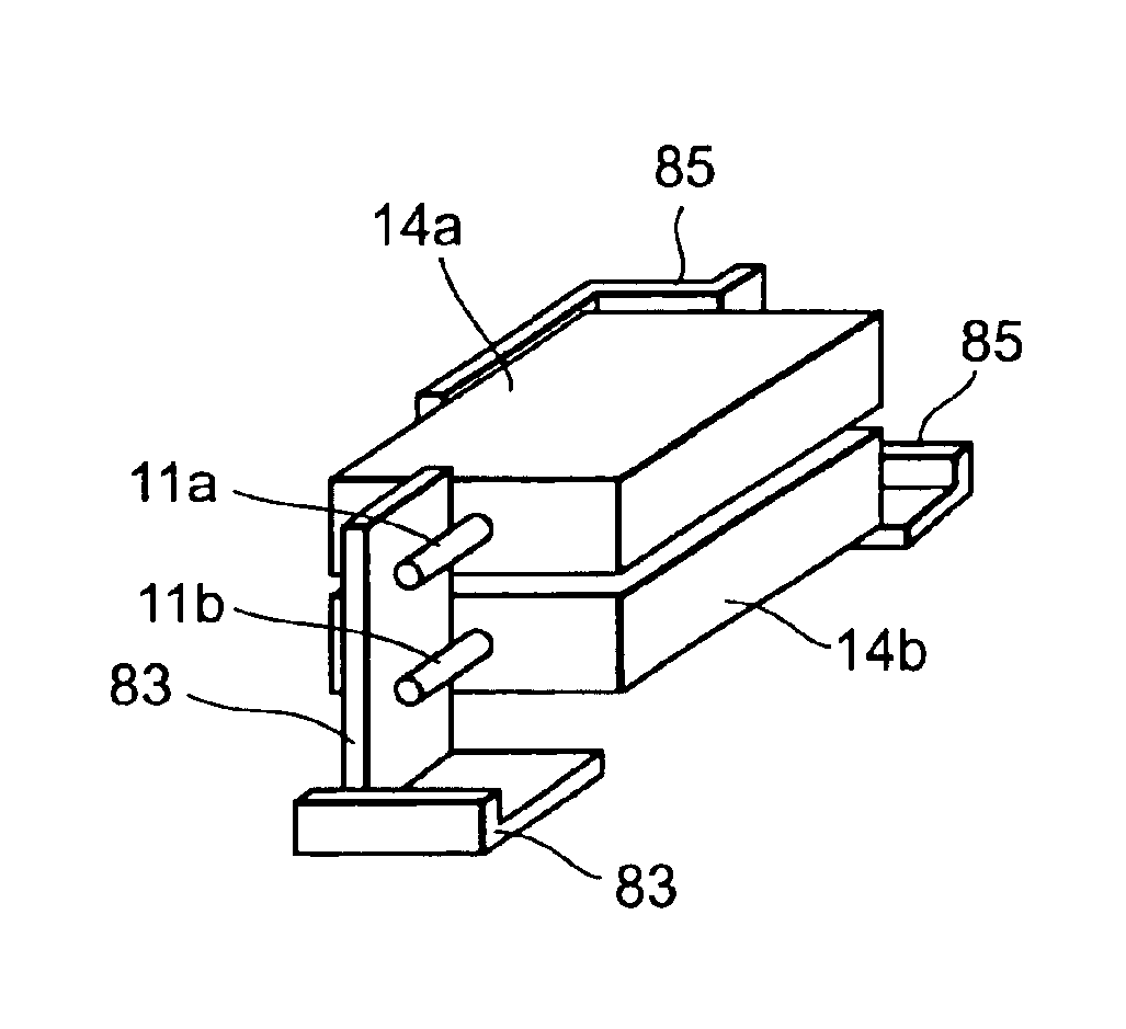
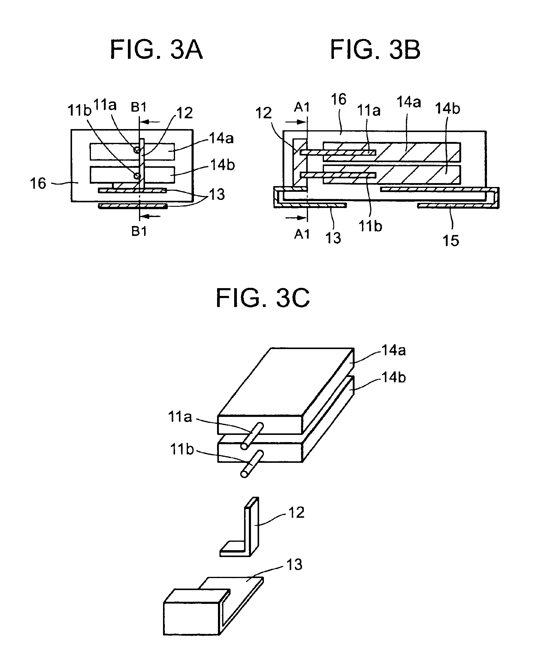
[0122]Referring to FIG. 3, there is shown a solid electrolytic capacitor according to the present invention. FIG. 3A, FIG. 3B, and FIG. 3C are a cross-sectional view taken on line A1—A1, a cross-sectional view taken on line B1—B1, and a partial exploded diagram shown by means of a perspective view, respectively. While cut areas are indicated by hatching in the cross sections, portions on the other side of exterior coating resin are shown as if the exterior coating resin were transparent.

[0123]There are shown anode leads 11a and 11b, an anode connecting piece 12, an anode terminal 13, capacitor elements 14a and 14b, a cathode terminal 15, and exterior coating resin 16.

[0124]First, the capacitor elements are described below. The capacitor elements 14a and 14b are in the thin-type pellet shape, thereby reducing an ESR of a single capacitor element. In other words, an ESR value depends upon a skin effect in a high frequency domain exceeding 100 kHz, and therefore the thin type is effect...

second embodiment

[0133]Referring to FIG. 4, there is shown a solid electrolytic capacitor according to the present invention. FIG. 4A, FIG. 4B, and FIG. 4C are a cross-sectional view taken on line A2—A2, a cross-sectional view taken on line B2—B2, and a partial exploded diagram shown by means of a perspective view, respectively.

[0134]There are shown an anode connecting piece 22, an anode terminal 23, and a cathode terminal 25. Other reference numerals are the same as in FIG. 3.

[0135]In the second embodiment, the anode connecting piece 22, the anode terminal 23, and the cathode terminal 25 differ from those in the first embodiment in the shapes, while others are substantially the same as the first embodiment.

[0136]The anode connecting piece 22, which is an L-shaped strip as shown in FIG. 4C, is welded to the anode leads 11a and 11b of a wire type by laser or resistance welding. Furthermore, the anode connecting piece 22 is welded to the anode terminal 23 of a bent strip type, too.

[0137]On the other h...

third embodiment

[0141]Referring to FIG. 5, there is shown a first solid electrolytic capacitor according to the present invention. FIG. 5A, FIG. 5B, and FIG. 5C are a cross-sectional view taken on line A3—A3, a cross-sectional view taken on line B3—B3, and a partial exploded diagram shown by means of a perspective view, respectively.

[0142]There are shown an anode connecting piece 32, an anode terminal 33, and a cathode terminal 35. Other reference numerals are the same as in FIG. 3 and FIG. 4.

[0143]In the third embodiment, the anode connecting piece 32, the anode terminal 33, and the cathode terminal 35 differ from those of the first embodiment and the second embodiment in the shapes, while others are substantially the same as these embodiments.

[0144]The anode connecting piece 32 in the bent shape as shown in FIG. 5C (the shape in which one of rectangular portions at both ends is further bent outwardly at an angle of 90 degrees among three rectangular portions formed by a strip bent into a horsesho...


PUM

PropertyMeasurementUnit
Angleaaaaaaaaaa
Angleaaaaaaaaaa
Lengthaaaaaaaaaa

Abstract

A solid electrolytic capacitor having at least two capacitor elements using a valve action metal, such as tantalum or niobium, and laminated in a direction perpendicular to a mounting surface of a substrate. The capacitor elements have a width parallel to the mounting surface of the substrate greater than a thickness perpendicular to the mounting surface of the substrate, and an anode terminal is connected with anode leads led out to at least one side of an anode body made of the valve action metal generally in parallel to the mounting surface of the substrate. A cathode layer on a dielectric oxide film of the anode body is connected to a cathode terminal and is coated with exterior coating resin with a part of the anode terminal and a part of the cathode terminal exposed.

Description

[0001]The present application claims priority to prior Japanese application JP 2003-42415, the disclosure of which is incorporated herein by reference.BACKGROUND OF THE INVENTION[0002]The present invention relates to a solid electrolytic capacitor and a method of manufacturing the same.[0003]Conventionally, a solid electrolytic capacitor, manufactured with the use of tantalum or the like for a valve action metal, has been used for a power supply circuit of a CPU since it is compact and has a large capacitance and a superior frequency characteristic.[0004]Recently, there has been a demand for further improving the frequency characteristic. Therefore, a solid electrolytic capacitor with a conductive polymer used for a cathode layer has been developed against the conventional solid electrolytic capacitor with manganese dioxide used for a cathode layer. Thereby, an equivalent series resistance (hereinafter, referred to as ESR) has been improved and reduced to less than or equal to one-t...

Claims


Application Information

Patent Timeline
IPC IPC(8): H01G9/00H01G9/04H01G9/004H01G9/012H01G9/008H01G9/14H01G9/15H01G9/042H01G9/10
CPCH01G9/012H01G9/042H01G9/14H01G9/26H01G9/10Y10T29/417
Inventor ARAI, SHINJIKAYAMORI, TAKAHIRO
Owner TOKIN CORP
Why Eureka
Try Eureka