Method of manufacturing a thin piezo resistive pressure sensor

a resistive pressure sensor and piezo technology, applied in the field of pressure sensors, can solve the problems of manufacturing techniques failing to produce pressure sensors with the desired sensitivity and robustness, and achieve the effect of reducing the thickness of the diaphragm wafer and small width

Inactive Publication Date: 2005-07-05
ROSEMOUNT AEROSPACE
View PDF20 Cites 70 Cited by
  • Summary
  • Abstract
  • Description
  • Claims
  • Application Information

AI Technical Summary

Benefits of technology

[0004]The present invention includes pressure sensors that are relatively thin, robust and have a relatively small width, and methods for manufacturing such pressure sensors. The pressure sensors of the present invention may be used in biological and medical procedures. However, the pressure sensors of the present invention are not restricted to such use and can be used in nearly any setting where pressure measurements are desired. In one embodiment, the invention is a method for forming a sensor including the steps of providing a base wafer and forming a sensor cavity in the base wafer. The method further includes the step of coupling a diaphragm wafer to the base wafer, the diaphragm wafer including a diaphragm portion and a sacrificial portion. The diaphragm wafer is coupled to the base wafer such the diaphragm portion generally covers the sensor cavity. The method further includes the steps of reducing the thickness of the diaphragm wafer by removing the sacrificial portion, and forming or locating at least one piezo resistive portion on the diaphragm portion.
[0005]In another embodiment the invention is a p

Problems solved by technology

As the size of pressure sensors are reduced, many existing manufacturing techniqu

Method used


Image

  • Method of manufacturing a thin piezo resistive pressure sensor
  • Method of manufacturing a thin piezo resistive pressure sensor
  • Method of manufacturing a thin piezo resistive pressure sensor

Examples


Embodiment Construction

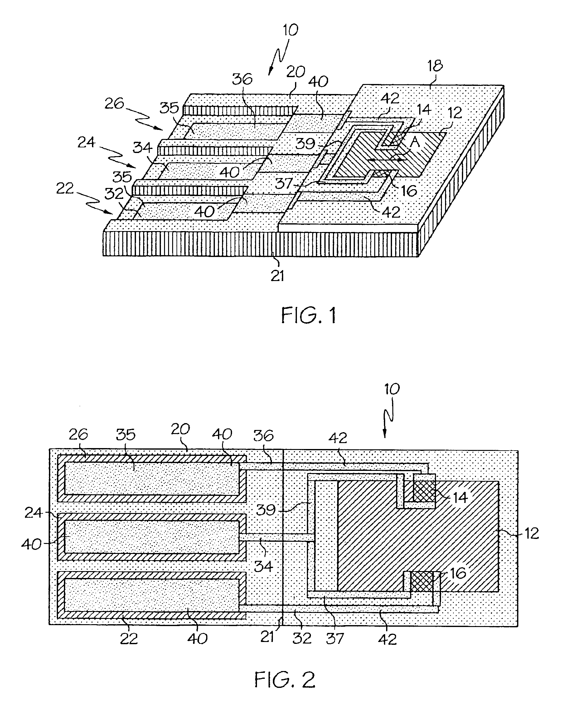
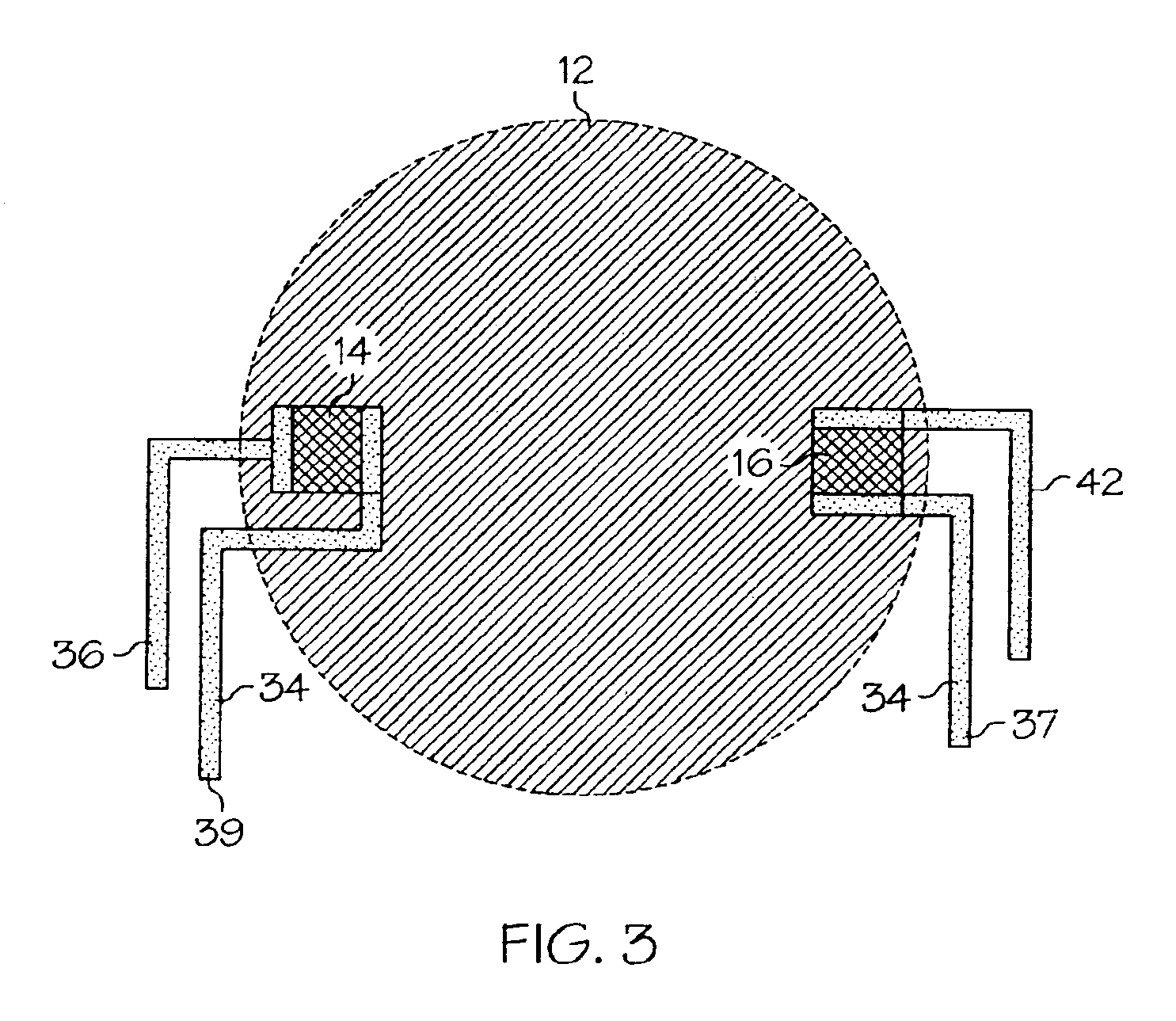
[0018]As shown in FIGS. 1 and 2, in one embodiment the pressure sensor 10 of the present invention includes a relatively thin, deflectable diaphragm 12 and a pair of piezo resistors 14, 16 located on the diaphragm 12. In the embodiment of FIG. 1, the diaphragm 12 is generally square in top view, although the diaphragm 12 may assume various other shapes (including circular, rectangular, etc.) without departing from the scope of the present invention. The diaphragm 12 is preferably, although not necessarily, made of single crystal silicon, and has a crystal plane orientation indicated by the arrow A. In this case, one of the piezo resistors 14, 16 may be located and aligned to sense strain of the diaphragm in a direction parallel to the crystal plane orientation A such that its resistance decreases when the diaphragm 12 is strained, and the other piezo resistor 14, 16 may be located and aligned to sense strain of the diaphragm 12 in a direction perpendicular to the crystal plane orien...


PUM

PropertyMeasurementUnit
Thicknessaaaaaaaaaa
Electrical conductoraaaaaaaaaa
Energyaaaaaaaaaa

Abstract

A method for forming a sensor including the steps of providing a base wafer and forming a sensor cavity in the base wafer. The method further includes the step of coupling a diaphragm wafer to the base wafer, the diaphragm wafer including a diaphragm portion and a sacrificial portion. The diaphragm wafer is coupled to the base wafer such the diaphragm portion generally covers the sensor cavity. The method further includes the steps of reducing the thickness of the diaphragm wafer by removing the sacrificial portion, and forming or locating at least one piezo resistive portion on the diaphragm portion.

Description

BACKGROUND OF THE INVENTION[0001]The present invention is directed to pressure sensors and method for manufacturing pressure sensors, and more particularly to thin piezo resistive pressure sensors and methods for manufacturing thin piezo resistive pressure sensors.[0002]Piezo resistive sensors are widely used to sense the pressure of various mediums. Small or miniature piezo resistive pressure sensors are often mounted on a guide wire or catheter such that the pressure sensor can be inserted into small volumes to measure the pressure of fluids inside the volume. For example, a guide wire or catheter with a piezo resistive pressure sensor mounted thereon can be inserted into biological flow paths, such as arteries and vessels, and are particularly used in coronary arteries during angioplasty procedures.[0003]There is an increasing need to advance guide wires and catheters into smaller vessels, and a corresponding need for smaller pressure sensors. As the size of pressure sensors are ...

Claims


Application Information

Patent Timeline
IPC IPC(8): G01L9/00
CPCG01L9/0055Y10T29/49082Y10T29/42
Inventor IZADNEGAHDAR, ALAINSIEKKINEN, JAMESESTRADA, HORACIO V.BOGGS, BRADNAGY, MICHAELSTARK, KEVIN
Owner ROSEMOUNT AEROSPACE
Why Eureka
Try Eureka