This process is labor intensive and therefore expensive.
Since this process of hand transplanting is not economical, several mechanical methods for transplanting the seedlings from the smaller cells to larger containers have been developed.
It is a
time consuming, labor intensive endeavor that is subject to any of the many possible errors that may arise when an individual is performing a repetitive task for long periods of time.
The use of the propagule plug punch machine, however, did not come without its own limitations.
Application limitations of existing plant transplant technology, including the inability of propagule plug punch machine systems to transplant into more than one (or a very few) adolescent plant tray (or output tray) configuration severely compromise the efficiency of the plant transplant process—and of the nursery business to which such process is vitally important.
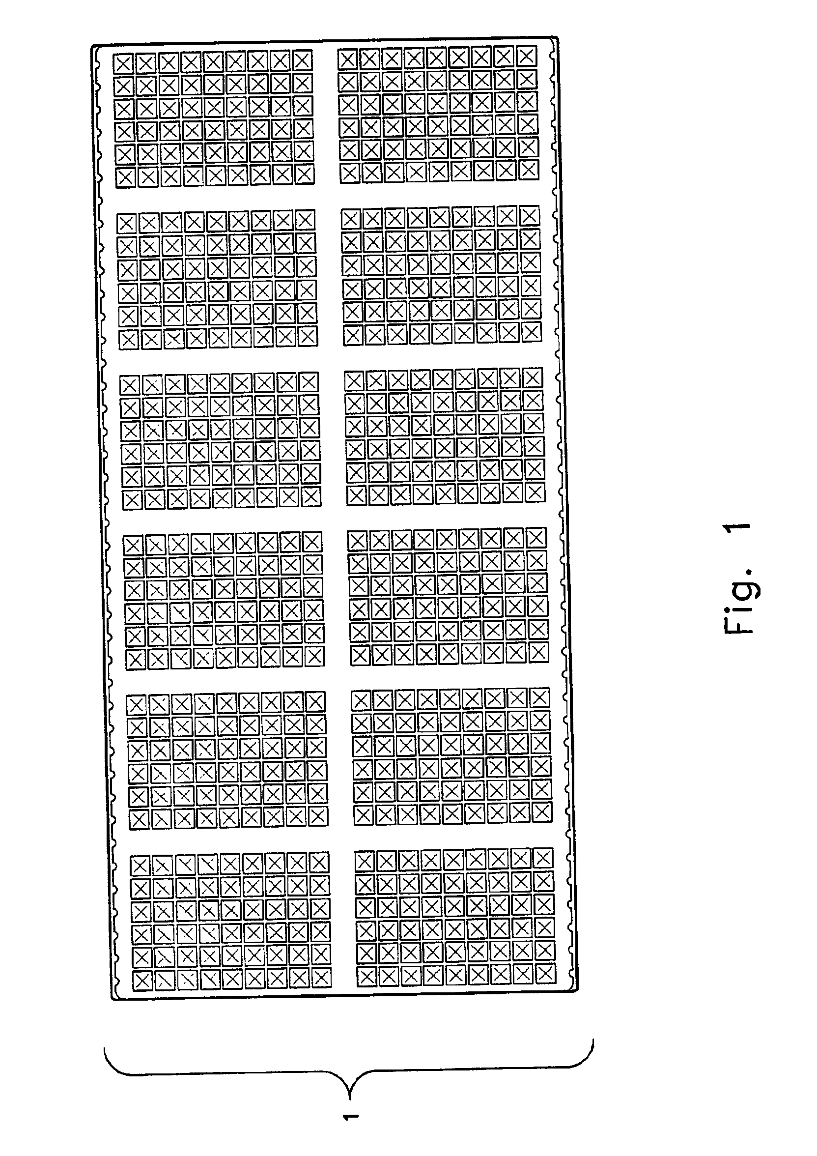
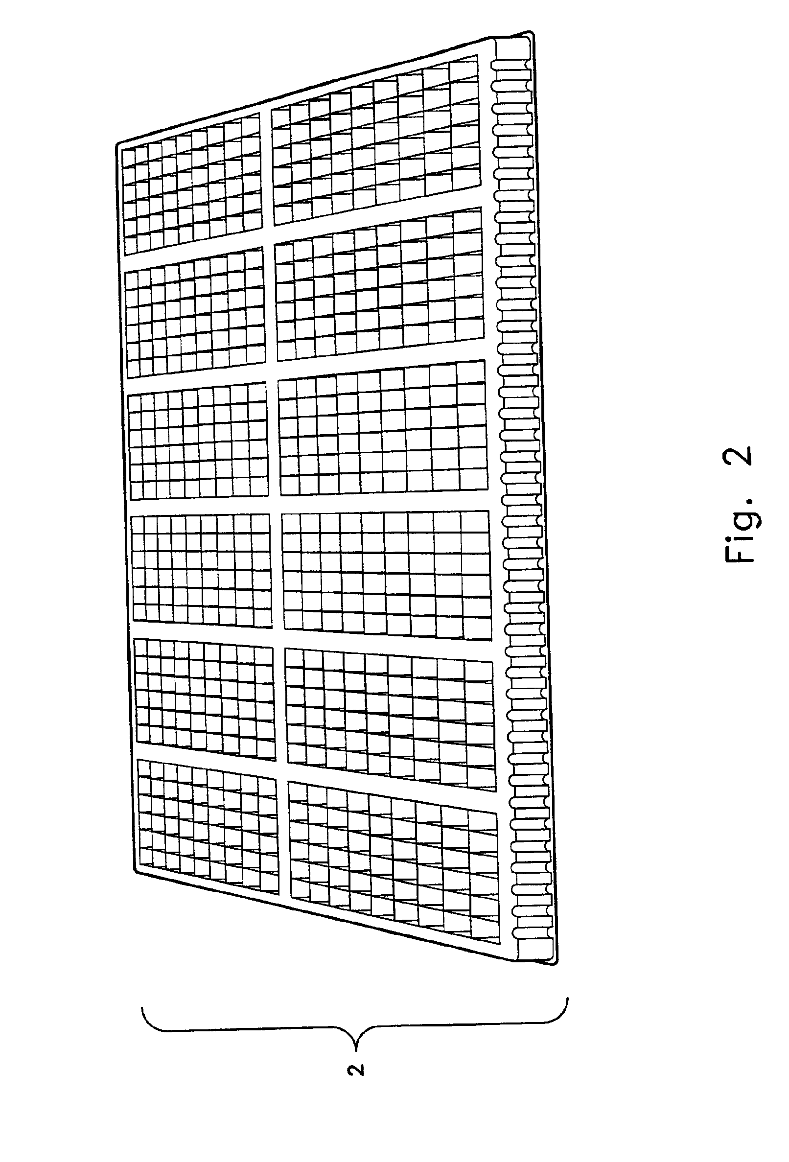
Such application limitations are due at least in part to the very limited selection of propagule plug trays (or input trays)
usable by the propagule plug punch machines and to the fact that the only available such trays exhibit a clustered (or areally discontinuous) arrangement of propagule plug containers.
However, in practice, the 2×6, 12-06 finished tray is the only finished tray conventionally used with the propagule plug punch machines, resulting in a severe limitation on the increase in transplanting efficiency that the punch machine might otherwise afford.
This practical application limitation is due in large part to the limited availability of different plant punch element assemblies (note that a plant punch element
assembly refers to a set of punch elements that may be arranged in a pattern, and each connected at one part (e.g., a terminus) to a plate or other structure that maintains the relative positioning of the punch elements during the punch or transplanting process; a punch element
assembly may be identified via a punch plate PIN).
In practice, with only one available propagule plug tray, and with its use to fill only one finished tray configuration, conventional propagule plug machine systems are extremely limited.
If not, the costly traditional hand transplanting methods were the only available alternative.
A further related problem associated with the existing propagule plug punch machine systems has to do with the uncertainty as to how many of the two row, six column cluster propagule plug trays (which exhibited the only configuration that the traditional propagule plug punch machine
system could work with) a nursery should optimally plant to accommodate any orders from distributors that may later arise (often orders that needed to be filled quickly).
Often, a nursery found itself with significantly more or fewer than an optimal number of planted propagule plug trays and suffered costly losses associated with such incorrect estimates.
Such a tray would reduce the risk that a forecasting error as to expected demand for a certain finished tray configuration would compromise
process efficiency.
This tray exhibits the clustered design that limits the compatibility of propagule transplant trays, specifically with regard to which finished or adolescent plant trays a plant punch machine using such propagule transplant trays punches into.
Yet another problem associated with the conventional method of using a punch machine to transplant propagules (and / or propagule plugs) has to do with the design of the propagule punch pins (or, more generally, the plant punch elements).
Use of conventional punch plant elements, when compared with use of the modified punch plant elements disclosed herein, result, e.g., in an increased damage to the transplant propagule or plant, which in turn compromises yield.
Propagules often suffer
impact and compression injuries and associated damage upon
receipt of the force imparted by the plant punch element during a transplant punch event.
A related problem stems from the flat, planar nature of the surface of the punch element head that first contacts the plant and / or the
growth medium (e.g., soil) in which the plant is situated.
Too often, the direct, non-diverting nature of the
impact causes unacceptably high amounts of crushing damage to the transplanted plants.
However, there appears to have been no attempt to modify the plant punch elements (or the manner in which they are used) from conventional design and practice in any manner in order to improve, e.g., yield or
survivability of the transplanted propagule.
Further, even if there were options in the design or use of plant punch elements, conventional plant transplanters (such as plant punch machines) provide no allowance for interchanging by a user of one punch element with another punch element having a preferred design for an indicated species and transplant modality.
Some seedlings may have been too small or too large to be successfully transplanted using a mechanical transplanter.
This may have resulted in
greenhouse operators
purchasing seedlings that cannot be used, thereby decreasing the yields of finished containers to seedlings.
Some seedlings may have been transplanted using this method, but because of mechanical damage to the
seedling experienced during the mechanical transplanting process, the
seedling later dies.
This may result in
greenhouse operators replacing the dead plant by hand.
This can be very labor intensive and cost inefficient.
This reduces the yield of the expected finished containers.
Greenhouse production costs often exceed 70% of the overall product costs.
However, none of these patents appears to disclose a large number of propagule containers that is operationally compatible with a numerically significant number of alternative adolescent plant tray configurations, as but one patentably significant feature.
One problem that
greenhouse operators struggle with is that
seedling producers have not previously been producing seedlings specifically grown to be transplanted with a mechanical transplanter.
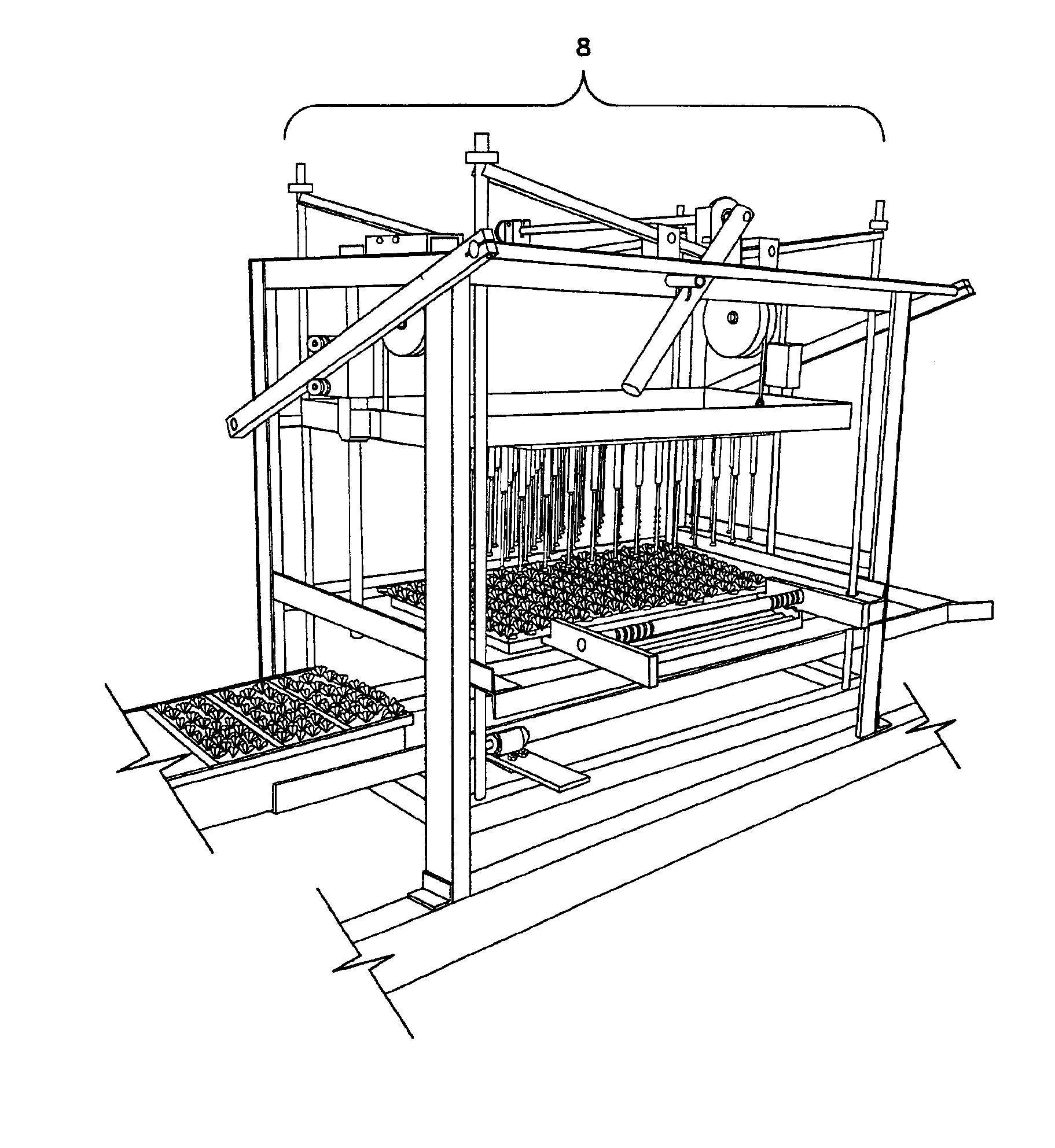
For example, one of the problems with this punch-down method of transfer is that the seedling can often be put under pressure as it is punched down through the seedling tray and into the new larger container's media as shown in U.S. Pat. Nos. 3,799,078 and 3,820,480.
This method uses a very
small cell for the seedling, which can result in the transfer of an immature seedling with a small
root system in a small amount of rooting media.
Because of the extremely small size of the individual cells, the seedlings can often be damaged during the punch out process.
Because of the high-density number of cells per tray, seedling leaves can be damaged because they do not often fit properly though the very
small cell.
This damage to the seedling can provide a wound for
disease or insects, which can reduce the vigor of the transplanted plant or even cause death.
The seedling's roots and media may be punched (or forcibly punched) into the new larger container's media potentially resulting in tearing and crushed roots.
Torn and crushed roots allow
disease and insects a
point of entry, which may reduce seedling vigor and may lead to death of the seedling in the new, larger container.
Further, the amount of rooting media is often extremely small.
Because of the small amount of media usually available for the seedling to root into, the
root system of the seedling is often small and fragile and therefore subject to tearing or damage that may provide a wound for
disease or reduce the overall
root volume available to support the plant.
Seedlings with damaged, diseased roots usually have reduced vigor and increased mortality rates.
All this may require the greenhouse operator to replace the dead plants or discard the container as unsalable.
Small, immature seedlings have a higher
mortality rate—often as high as 10-15% depending on variety of seedling—which dramatically reduces the transplant yield and increases production costs.
Sometimes the seedling tray and larger container may often not be compatible, resulting in leftover seedlings that may either be thrown away or may need to be manually transplanted.
This may require greenhouse operators to either discard the left over seedlings or to discard the finished tray that is not completed causing additional expense in seed, growing media, trays, labor, greenhouse space, and overhead to manage product that will be discarded.
Another problem is that the leaf area and
leaf type of the seedling may not be coordinated with the mechanical aspect of the transplanting process.
This could result in a significant number of torn or damaged leaves on the seedlings as the transplanter transfers the seedling from the
small cell to the larger container.
This tearing or damage of the leaf may create a
point of entry for disease, or reduces the vigor of the seedling by reducing the
photosynthesis area so it either is stunted or dies in the larger container.
This may also reduce yields.
Another potential problem with the system described in U.S. Pat. No. 3,799,078 and U.S. Pat. No. 3,820,480 is that the ratio of the head of the punch-down device can be too large for the
cell dimensions.
This action may result in crushing and breaking of leaves and stems of the seedlings as it is punched down through the
cell into the larger container or tray.
As mentioned, crushed or broken leaves or stems may allow disease and insects at a
point of entry which can reduce seedling vigor and may lead to death of the seedling in a new, larger container.
This can require the greenhouse operator to replace the dead plants or discard the container as unsalable.
Another problem with the puncher head described in U.S. Pat. No. 3,799,078 and U.S. Pat. No. 3,820,480 may be that the puncher head may have a concave face.
This may significantly increase the likelihood that the puncher head will break or crush the leaves and / or stem of the seedling being transplanted.

