
Symmetrical multiple-slice computed tomography data management system

Active Publication Date: 2005-07-12
KONINKLIJKE PHILIPS ELECTRONICS NV
View PDF10 Cites 30 Cited by
  • Summary
  • Abstract
  • Description
  • Claims
  • Application Information

AI Technical Summary

Benefits of technology

[0018]One advantage of the present invention resides in a symmetric DMS configuration that reduces parasitic noise and provides for a more compact DMS.

Problems solved by technology

DMS modules for CT imaging in the past have had a number of deficiencies relating to bulkiness and excessive mass, complex and non-standardized electrical wiring, parasitic noise coupling, complex and difficult optical alignment, and overall system complexity.
The amount of electrical cabling involved is substantial.
Furthermore, there are many constraints on the arrangement of the electrical cabling.
In addition to spatial limitations on and near the rotating gantry, the electrical cabling is further constrained by electrical path length requirements.
Differences in the signal path lengths for transmitting the various detector outputs give rise to signal phase differences, data errors, different amounts of transmission noise, and signal delays due to differential signal transit times along paths of different lengths.
The analog signals are also susceptible to parasitic noise pick-up if the cabling runs close to electrically active components including the DMS electronics and the x-ray source.
This asymmetrical arrangement leads to signal path length differences.
The lack of modularity of conventional DMS modules can also lead to unnecessary component replacement.
The conventional DMS is typically heavy and bulky, as it includes a cast aluminum frame which supports separate substrates for the photodetectors (usually ceramic) and the remote electronic signal processing circuitry (usually arranged on printed circuit boards), massive quantities of cabling between the detector arrays and the signal processing circuitry, dedicated heaters and fans for temperature control, and electromagnetic shielding to reduce parasitic noise coupling onto the extensive electrical cabling.
The DMS weight and piecemeal construction also places limits on the attainable rotational speed of the gantry and on the data throughput, which in turn limit overall scan speed and the number of views per revolution.
The complexity of conventional DMS modules impacts reliability and frequently necessitates field servicing by trained personnel for routine maintenance operations such as replacing and realigning detector array elements.

Method used


Image

  • Symmetrical multiple-slice computed tomography data management system
  • Symmetrical multiple-slice computed tomography data management system
  • Symmetrical multiple-slice computed tomography data management system

Examples


Embodiment Construction

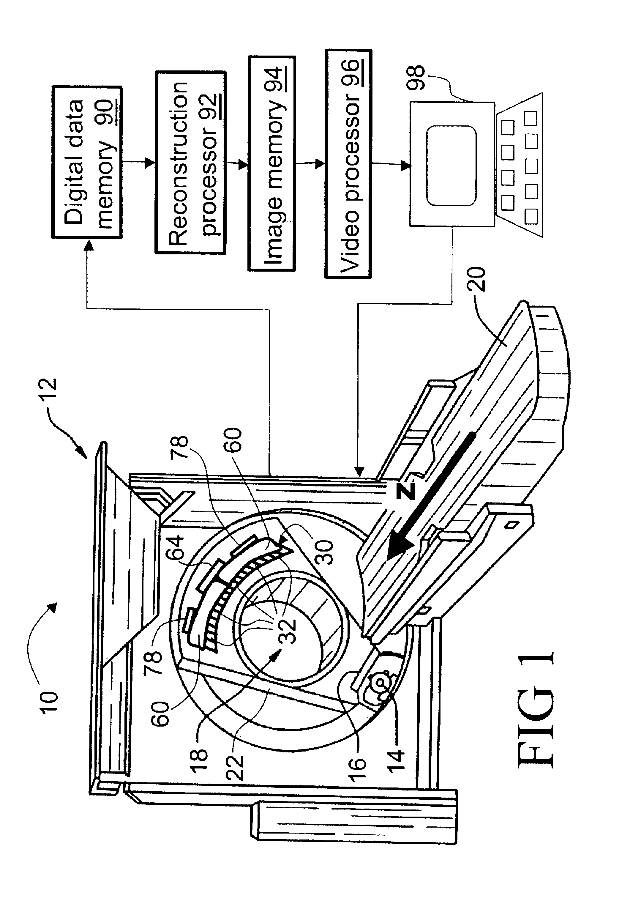
[0038]With reference to FIG. 1, a computed tomography (CT) imaging apparatus 10 includes a CT scanner 12 includes an x-ray source 14 and a collimator 16 that cooperate to produce a fan-shaped, cone-shaped, wedge-shaped, or otherwise-shaped x-ray beam directed into an examination region 18 which contains a subject (not shown) such as a patient arranged on a subject support 20. The patient support 20 is linearly movable in a Z-direction while the x-ray source 14 is rotatable on a rotating gantry 22.

[0039]In an exemplary helical imaging mode, the gantry 22 rotates simultaneously with linear advancement of the subject support 20 to effectuate a helical orbiting of the x-ray source 14 and collimator 16 about the examination region 18. However, other imaging modes can also be employed, such as a single- or multi-slice imaging mode in which the gantry 22 rotates as the subject support 20 remains stationary to effectuate a circular orbiting of the x-ray source 14 to acquire one or more axia...


PUM


Abstract

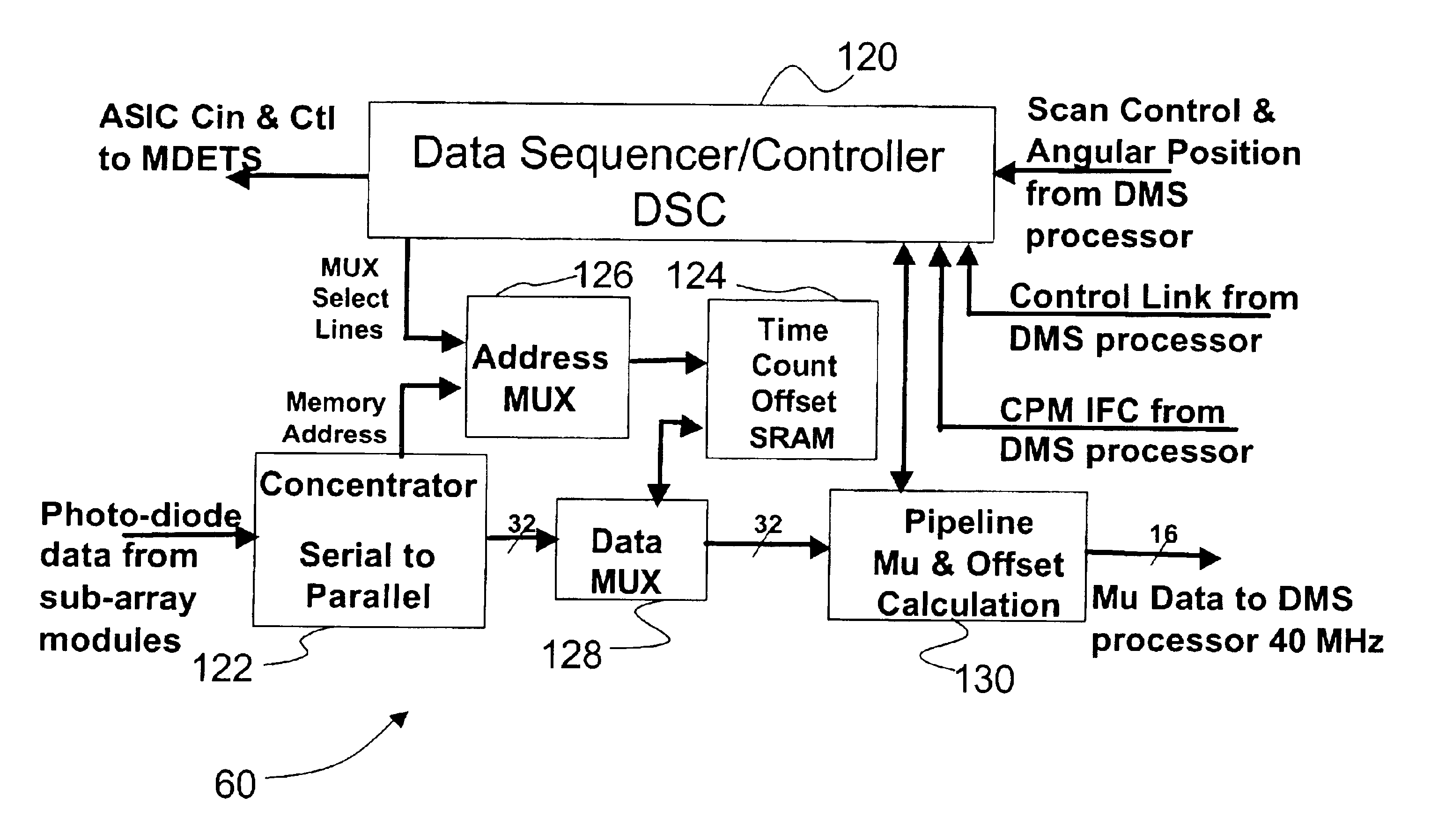
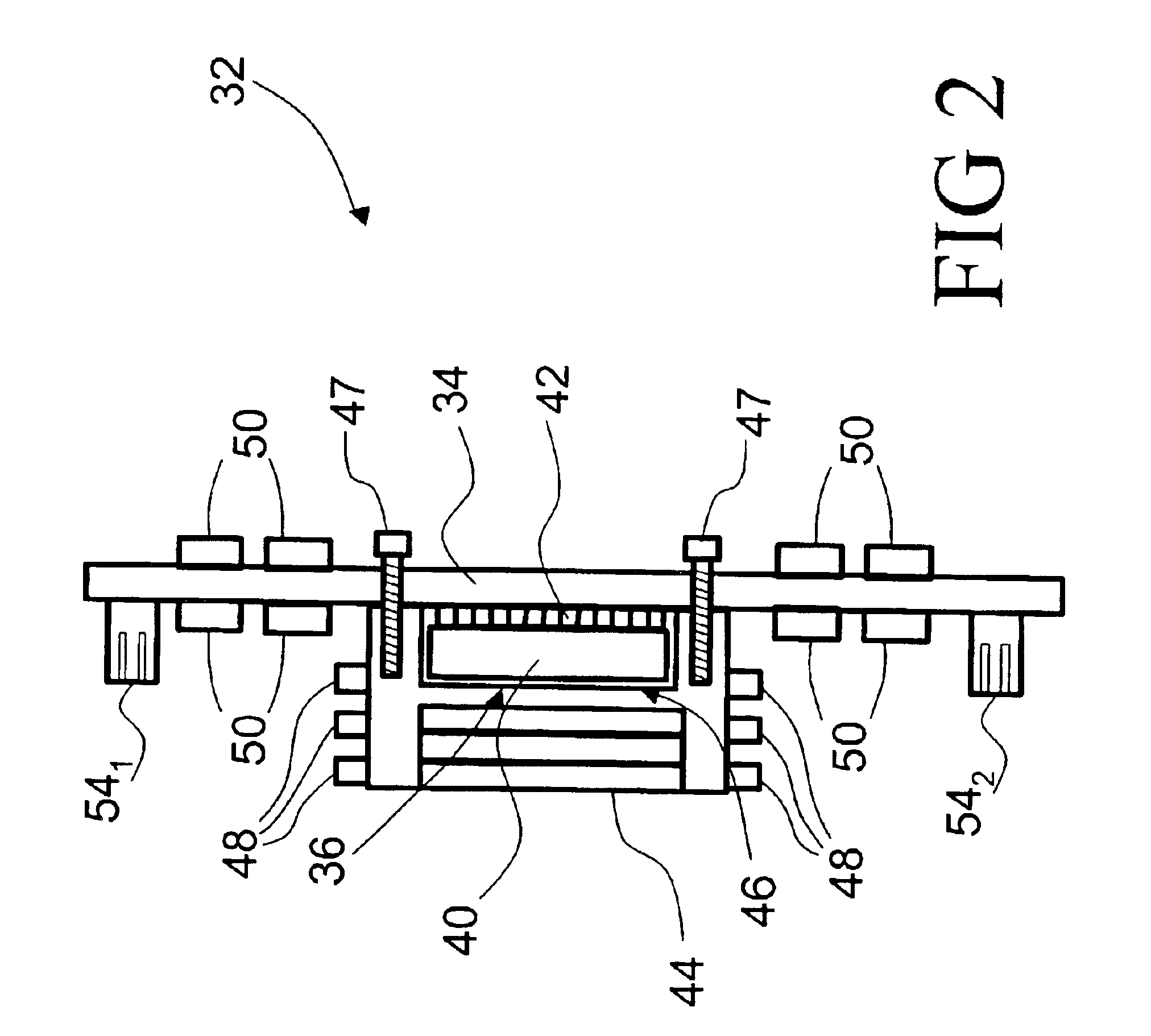
A data measurement system (DMS) (30) for a computed tomography (CT) scanner (12) includes a plurality of connectorized detector sub-array modules (32). Each detector sub-array module (32) includes: a scintillator (40) that produces scintillation events responsive to irradiation by x-rays; a photodetector array (42) arranged to detect the scintillations; and two symmetrically arranged signal connectors (541, 542) that transmit the photodetector signals. Symmetrically mounted pipeline cards (60) mate with the signal connectors (54) of each side of groups of the detector sub-array modules (32) to receive the photodetector signals. A processor (64) communicating with the pipeline cards (60) receives the photodetector signals from the pipeline cards (60) and constructs a DMS output from the photodetector signals.

Description

BACKGROUND OF THE INVENTION[0001]The present invention relates to the diagnostic imaging arts. It particularly relates to computed tomography imaging employing a two-dimensional detector array that enables rapid acquisition of volumetric imaging data, and will be described with particular reference thereto. However, the invention will also find application in other types of radiation detectors for a variety of imaging applications employing x-rays, visible light, or other types of radiation. The invention will further find application in non-imaging radiation detectors for radiological applications and the like.[0002]Computed tomography (CT) imaging typically employs an x-ray source that generates a fan-beam or cone-beam of x-rays that traverse an examination region. A subject arranged in the examination region interacts with and absorbs a portion of the traversing x-rays. A CT data measurement system (DMS) including a two-dimensional detector array in a cast frame assembly is arran...

Claims


Application Information

Patent Timeline
IPC IPC(8): A61B6/03G01T1/164
CPCA61B6/032A61B6/4085G01T1/1647A61B6/027
Inventor CHAPPO, MARC A.LUHTA, RANDALL P.BRUNNETT, WILLIAM J.
Owner KONINKLIJKE PHILIPS ELECTRONICS NV
Learn More