Wideband variable gain amplifier with high linearity operating in switch mode

a variable gain amplifier and wideband technology, applied in amplifiers, amplifiers with semiconductor devices/discharge tubes, amplifiers, etc., can solve the problems of limiting the improvement of linear characteristics using active elements, needing additional current and chip area, etc., and achieve excellent linearity and excellent amplification operation.

Active Publication Date: 2005-07-19
INTEGRANT TECH
View PDF6 Cites 14 Cited by
  • Summary
  • Abstract
  • Description
  • Claims
  • Application Information

AI Technical Summary

Benefits of technology

[0012]An object of the present invention is to provide a variable gain amplifier having an excellent linearity.
[0013]Another object of the present invention is to provide a variable gain amplifier that can perform an optimum operation in a high gain mode or a low gain mode.
[0014]Still another object of the present invention is to provide a variable gain amplifier having an excellent amplification operation at a wideband.

Problems solved by technology

For the variable gain amplifier disclosed in U.S. Pat. No. 5,949,286, however, since it employs the dummy amplifier to improve its linearity, there has been a problem in that additional current and chip area are needed, and in that there is a limit in improving linear-characteristics using an active element.

Method used


Image

  • Wideband variable gain amplifier with high linearity operating in switch mode
  • Wideband variable gain amplifier with high linearity operating in switch mode
  • Wideband variable gain amplifier with high linearity operating in switch mode

Examples


Embodiment Construction

[0029]Reference will now be made in detail to the preferred embodiments of the present invention, examples of which are illustrated in the accompanying drawings.

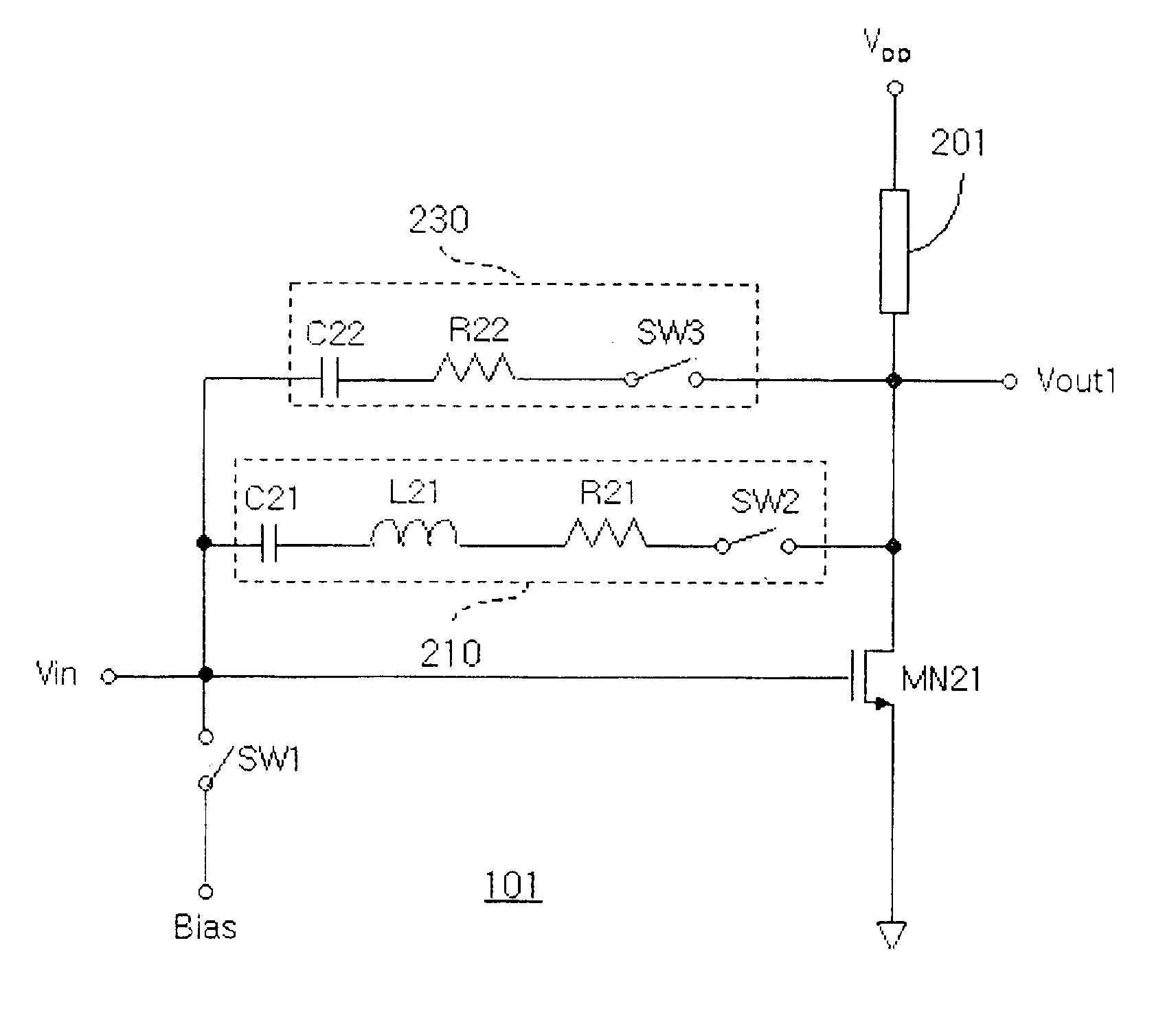
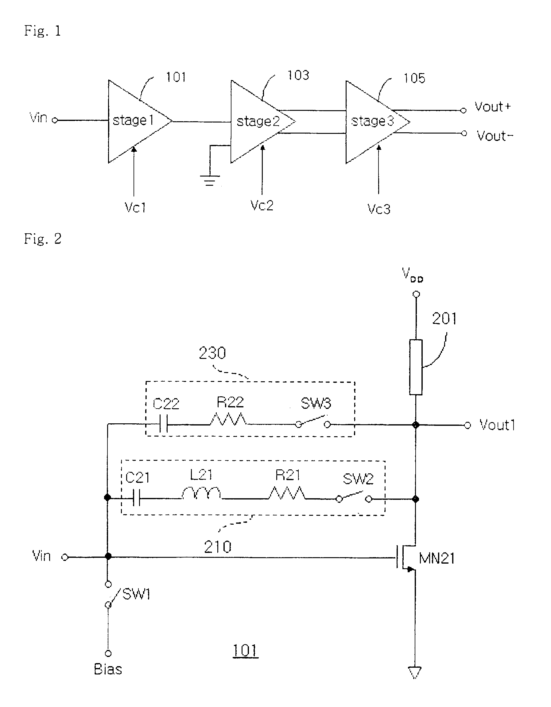
[0030]A variable gain amplifier according to the present invention employs a MOSFET transistor amplifier. The amplifier has a gate, a source and a drain. The MOSFET transistor has a property that the amount and direction of current flowing from its source to its drain, and vice versa are decided depending on the amount and polarity of a voltage applied to its gate. Such an amplifier may involve a bipolar junction transistor (BJT), a junction field effect transistor (JFET), a metal oxide semiconductor field effect transistor (MOSFET), a metal semiconductor field effect transistor (MESFET), and so on.

[0031]Furthermore, most of these amplifiers utilize two complementary devices that are complementary each other, i.e., a first complementary device, for example, an N type MOSFET, and a second complementary device, for example, a ...


PUM


Abstract

Disclosed is a wideband variable gain amplifier with high linearity that operates in a switch mode. The variable gain amplifier includes a first amplifier unit, a second amplifier unit and a third amplifier unit. The first amplifier unit includes an amplifier, a wideband-matching element, an attenuator and first switching means. The first amplifier unit supports a high gain mode operation and a low gain mode operation. In the high gain mode, the first switching means is short-circuited and an input signal is amplified with a high gain. It is thus possible to reduce noise characteristics of the entire system by a rear stage. In the low gain mode, the first switching means is opened and the input signal is attenuated by the attenuator without an amplification operation. It is thus possible to reduce a non-linearity occurring by the rear stage of the first amplifier unit. According to another embodiment of the present invention, only the first amplifier unit can be independently used in order to amplify a signal. Furthermore, a variable gain amplifier can be implemented by connecting various combinations of the second amplifier unit and the third amplifier unit at the rear of the first amplifier unit.

Description

BACKGROUND OF THE INVENTION[0001]1. Field of the Invention[0002]The present invention relates to a variable gain amplifier, and more particularly, to a wideband variable gain amplifier with high linearity that operates in a switch mode.[0003]2. Background of the Invention[0004]A variable gain amplifier refers to a device which functions to maintain a desired output signal level by controlling its gain. The variable gain amplifier is usually used in radio frequency-receiving devices in which a signal received through an antenna has a high dynamic range. In order for a signal of a constant level to be supplied to a base band terminal of the received signal, the variable gain amplifier must also have a high dynamic range.[0005]Many researches have been actively made so far on a variable gain amplifier, and hence various variable gain amplifiers have been proposed. Researches are in progress to increase the dynamic range of the variable gain amplifier and improve a linearity of a signal...

Claims


Application Information

Patent Timeline
Patent Type & Authority Patents(United States)
IPC IPC(8): H03G1/00H03G3/30
CPCH03F3/45197H03G1/007H03G3/30
Inventor CHO, YOUNG-HOKIM, BO-EUNKIM, BON-KEE
Owner INTEGRANT TECH
Why Eureka
Try Eureka