Casting steel strip

Inactive Publication Date: 2005-07-26
CASTRIP
View PDF12 Cites 130 Cited by
  • Summary
  • Abstract
  • Description
  • Claims
  • Application Information

AI Technical Summary

Benefits of technology

[0018]In an alternative embodiment, the first enclosure and the second enclosure may be separately sealed against ingress of atmospheric air, and water may be introduced into the first enclosure in form of a fine mist to produce an increased level of hydrogen gas therein while tending to avoid liquid water contact with the steel strip and the casting surfaces of the casting roll or rolls. Such water introduced as a fine mist

Problems solved by technology

When casting steel strip in a twin roll caster, the strip leaves the nip at very high temperatures of the order of 1400° C. and can suffer very rapid scaling due to oxidation at such high temperatures.
Such scaling may result in a significant loss of steel product.
Moreover, such scaling results in the need to descale the strip prior to further processing by pickling to avoid surface quality problems such as rolled-in scale, and causes significant extra complexity, cost and environmental concerns.
However, scaling of the hot strip material emerging from the strip caster progresses so rapidly that it may be necessary to install descaling equip

Method used


Image

  • Casting steel strip
  • Casting steel strip
  • Casting steel strip

Examples


Example

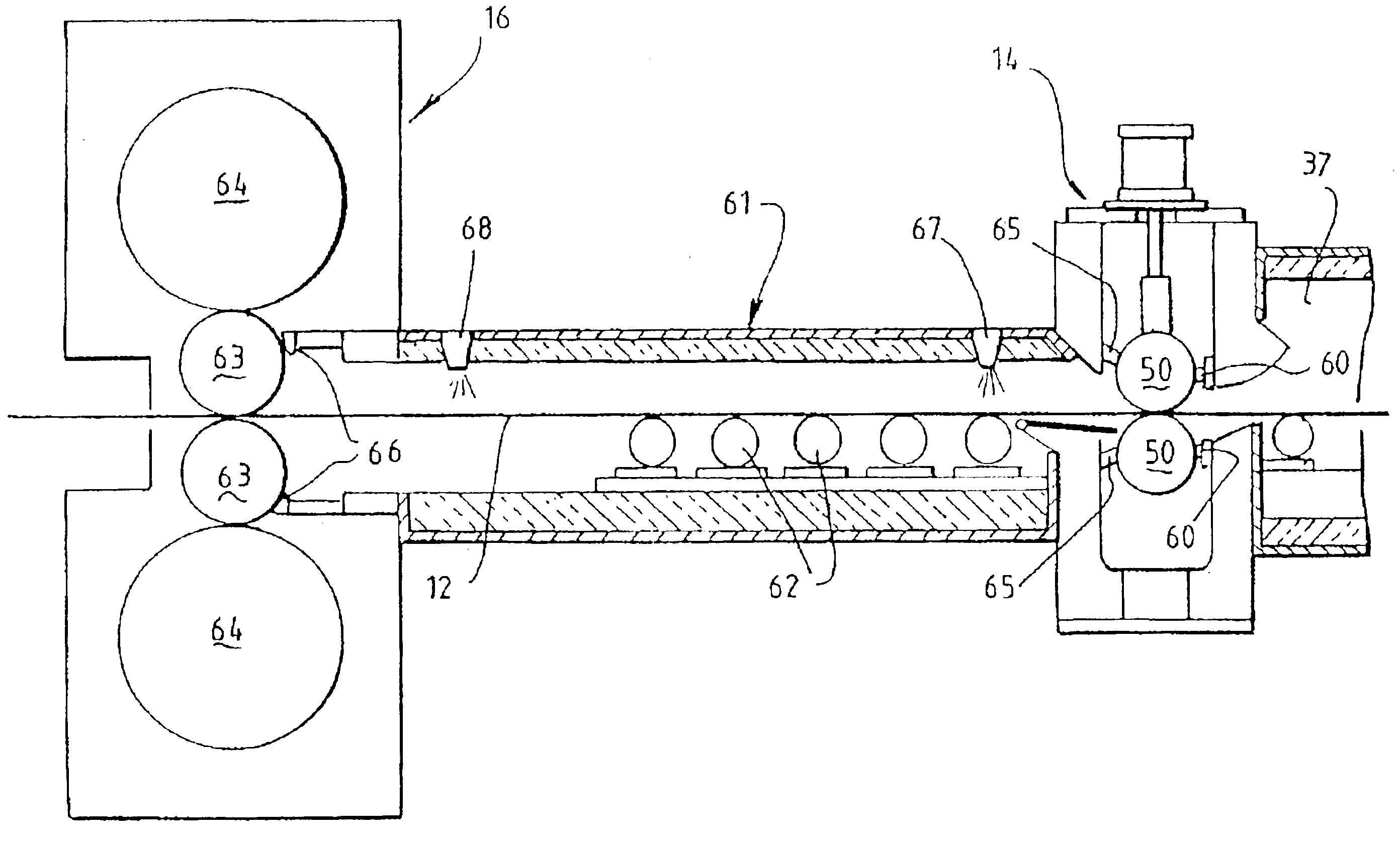
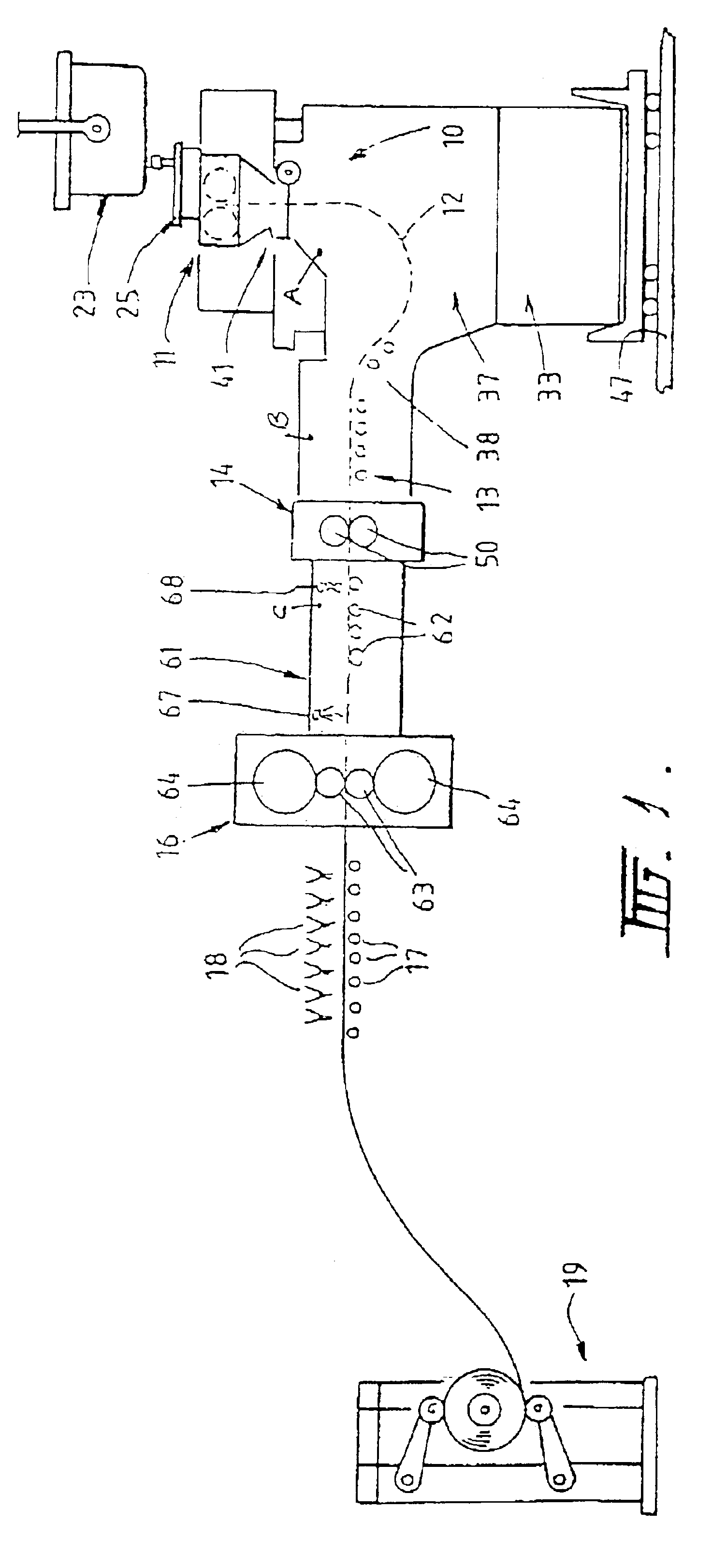
[0043]The casting and rolling installation illustrated in FIGS. 1 to 7 comprises a twin roll caster denoted generally as 11 that produces a cast steel strip 12 which passes in a transit path 10 across a guide table 13 to a pinch roll stand 14. After exiting the pinch roll stand 14, the strip passes to a hot rolling mill 16 in which it is hot rolled to reduce its thickness. The rolled strip exits the rolling mill and passes to a run out table 17 on which it may be force cooled by a fine mist from water jets 18 and thence to a coiler 19.

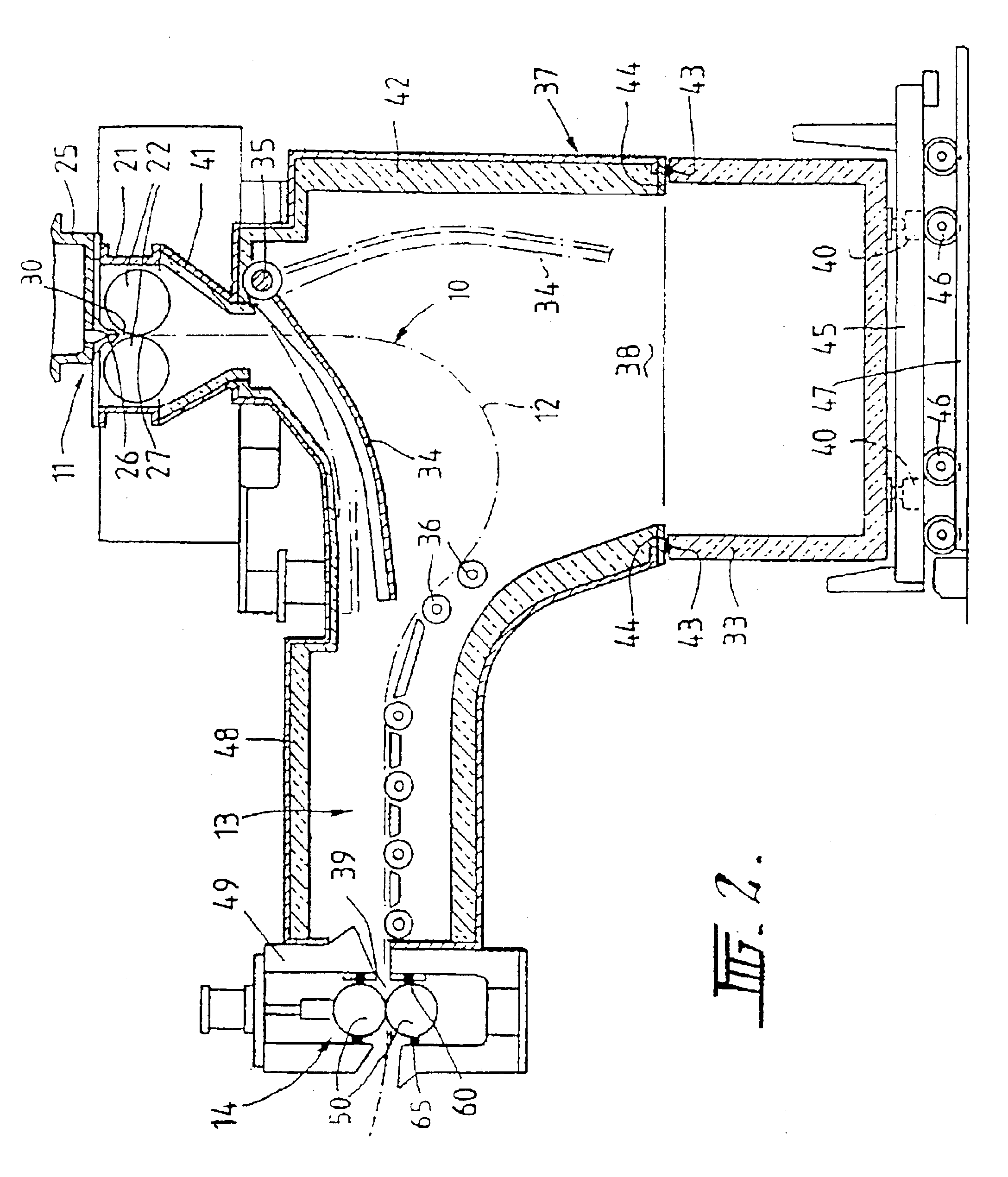
[0044]Twin roll caster 11 comprises a main machine frame 21 which supports a pair of parallel casting rolls 22 having casting surfaces 22A. Molten metal is supplied during a casting operation from a ladle 23 through a refractory ladle outlet shroud 24 to a tundish 25 and thence through a metal delivery nozzle 26 above the nip 27 between the casting rolls 22. Molten metal thus delivered forms a casting pool 30 supported on the casting surface 22A of the...


PUM

PropertyMeasurementUnit
Temperatureaaaaaaaaaa
Fractionaaaaaaaaaa

Abstract

Roll caster (11) produces thin steel strip (12) formed on casting surfaces (22A) of casting roll (22) that passes through first enclosure (37) adjacent casting roll surfaces (22A) and, optionally, thereafter second enclosure (61). Enclosure (37) and/or enclosure (61) may be fitted with spray nozzles (71,72) and/or (67, 68) operable to spray fine water mist adjacent strip (12) to produce hydrogen gas in enclosure (37) while tending to avoid liquid water contact with steel strip (12) and casting surfaces (22A). If hydrogen gas is produced only in enclosure (61), the two enclosures (37, 61) are interconnected so that gas can flow from enclosure (61) to enclosure (37). Enclosure (37) and, if present, enclosure (61) are sealed to maintain positive pressure and oxygen levels less than the surrounding atmosphere, and with the presence of hydrogen gas, reduce formation of scale on the strip in enclosure (37) and, if present, enclosure (61).

Description

RELATED APPLICATIONS[0001]This application is a continuation-in-part of application Ser. No. 10 / 121,567, filed Apr. 12, 2002 now U.S. Pat. No. 6,776,218, which is a pending continuation-in-part application of International Application PCT / AU00 / 01478 filed Nov. 30, 2000, which application claims priority to Australian Provisional Patent Application No. PQ4362, filed Nov. 30, 1999.BACKGROUND[0002]This invention relates to continuous casting of steel strip in a strip caster, particularly a twin roll caster.[0003]In a twin roll caster, molten metal is introduced between a pair of counter-rotated horizontal casting rolls which are internally cooled so that metal shells solidify on the moving roll surfaces and are brought together at the nip between them to produce a solidified strip product delivered downwardly from the nip. The term “nip” is used herein to refer to the general region at which the casting rolls are closest together. The molten metal may be poured from a ladle into a smal...

Claims


Application Information

Patent Timeline
IPC IPC(8): B21B9/00B22D11/06B22D11/14B21B1/46B21B39/00B21B1/26B22D11/12B22D11/124
CPCB21B1/463B21B9/00B22D11/0622B22D11/0697B22D11/148B21B1/26B21B39/006B22D11/124B22D27/003
Inventor BLEJDE, WALTER N.GLUTZ, ANDREW
Owner CASTRIP
Why Eureka
Try Eureka