Fiber-optic matrix switch using phased array acousto-optic device

a phased array acousto-optic device and fiber-optic matrix technology, applied in the direction of optics, optical light guides, instruments, etc., can solve the problems of low reliability, slow response time of electro-mechanical fo switches, and inability to operate in the microsecond range, even with mems technology, to achieve the effect of controlling the strength of coupling

Inactive Publication Date: 2005-07-26
MVM ELECTRONICS
View PDF8 Cites 55 Cited by
  • Summary
  • Abstract
  • Description
  • Claims
  • Application Information

AI Technical Summary

Benefits of technology

[0011]With the arrangement of FO switches as shown in FIG. 3, 4 or 5, efficient AO interaction occurs with only one optical beam incident at a particular angle to the selected phased array transducer. Therefore, one phased array transducer can deflect an optical beam from a selected fiber to a range of output angles controlled by the RF frequency. However, each optical beam is deflected in...

Problems solved by technology

Electro-mechanical movement is characterized by slow response time and low reliability.
Electro-mechanical FO switches, even with MEMs technology, cannot operate in the microsecond range.
Earlier patents on 2×2 FO matrix switch that utilized a single AO deflector with zero and first-order deflected beams did not address inadequate (<50 dB) isolation problem.
In other instances FO matrix switches required more than...

Method used


Image

  • Fiber-optic matrix switch using phased array acousto-optic device
  • Fiber-optic matrix switch using phased array acousto-optic device
  • Fiber-optic matrix switch using phased array acousto-optic device

Examples


Embodiment Construction

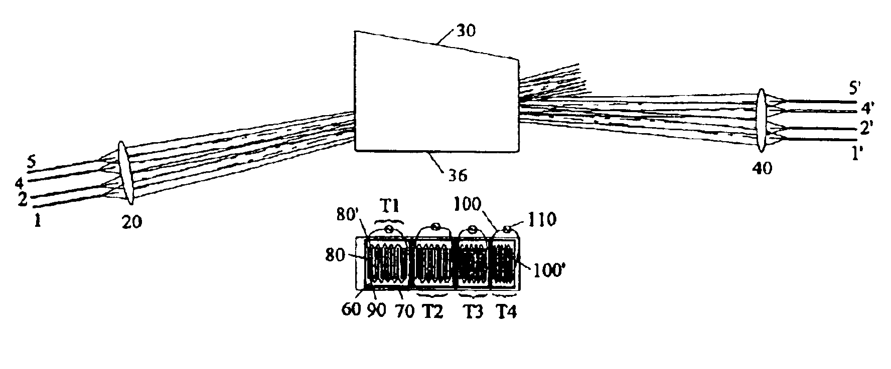
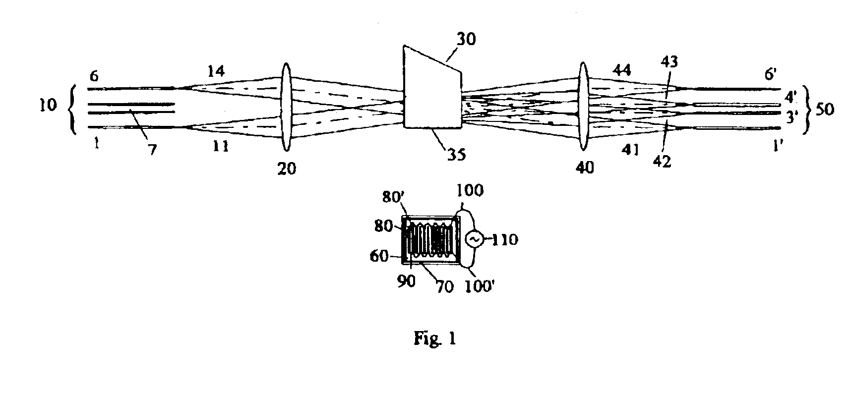
[0019]FIG. 1 shows one of the preferred embodiments of the current invention. The transducer 35 is fabricated with piezoelectric plate 60 bonded to an AO device material body 30 with bonding agent 70 consisting of several thin metallic layers deposited by vacuum or plating process. The bonding layer in the phased array transducer is usually floated, meaning the electrode is not connected at any place. The transducer's active area is defined by the top electrode pattern. In the preferred embodiment the phased array pattern is selected for the top electrode. The phased array pattern consists of periodic metallic film stripes 80 and 80″ with gaps 90. The pattern is chosen to have a fill factor in the range of 0.1 to 0.9 to optimize the coupling between the RF and acoustic field. This pattern is known as “inter-digital pattern.” The alternate electrodes are connected by thin wires 100 and 100″ forming two groups and are excited with RF drive signal 110 while the bottom metallic layer of...


PUM


Abstract

A high-speed high-isolation fiber-optic matrix switch using only one acousto-optic device with phased array transducers is disclosed. Previously disclosed fiber-optic switches either required spatially separated more than one acousto-optic devices making them complex, hard to align and expensive or could not achieve high-isolation and low-insertion loss performance. A simple structure of 2×2 fiber-optic matrix switch with one phased array transducer as disclosed here is expected to make acousto-optic based fiber-optic switches more attractive than similar MEMs based switches. Use of shared lens instead of individual lenses at the input and output fiber array is expected to further reduce complexity and cost of the acousto-optic based fiber-optic switches.

Description

BACKGROUND OF INVENTION[0001]This invention is in the field of active Fiber-Optic (FO) components and specifically in the field of FO matrix switch. This disclosure of my invention describes methods of implementing several functions in FO systems without any moving parts. These functions include, for example, N×N matrix switching with variable coupling, variable strength multiple port coupling, electronically variable attenuation, frequency shifting, and wavelength selection. All FO systems and networks encompassing telecommunication, data-communication, remote sensing, etc. utilize switching and other above-mentioned functions. My invention could be easily incorporate in those FO systems and would enhance system performance. The invention disclosed here falls into the specific category of high speed, high isolation, no moving parts phased array Acousto-Optic (AO) FO matrix switches.[0002]Electro-mechanical movement of reflective or refractive elements commonly performs switching fu...

Claims


Application Information

Patent Timeline
IPC IPC(8): G02B6/35G02F1/29G02F1/33G02B6/32
CPCG02F1/332G02B6/32G02B6/351G02B6/3526G02B6/3546G02B6/3578
Inventor SHAH, MANHAR L.
Owner MVM ELECTRONICS
Why Eureka
Try Eureka