Ultra-thin copper foil with carrier, method of production of same, and printed circuit board using ultra-thin copper foil with carrier

a technology carrier, which is applied in the direction of insulating substrate metal adhesion improvement, heat measurement, instruments, etc., can solve the problems of easy wrinkles, creases, and low mechanical strength of ultra-thin copper foil, and achieve stable peeling strength, easy peeling apart, and reduced pinholes

Inactive Publication Date: 2005-08-02
FURUKAWA ELECTRIC CO LTD
View PDF9 Cites 25 Cited by
  • Summary
  • Abstract
  • Description
  • Claims
  • Application Information

AI Technical Summary

Benefits of technology

[0015]An object of the present invention is to provide an ultra-thin copper foil with a carrier having a peeling layer able to withstand even high temperature working such as when using a high heat resistant resin, enabling the carrier foil and the ultra-thin copper foil to be easily peeled apart by a stable peel strength by keepin

Problems solved by technology

As a result, the verticality of the side walls of the interconnect patterns formed is ruined.
However, a thin copper foil (ultra-thin copper foil) is low in mechanical strength, easily wrinkles, is creased, and sometimes tears when producing a printed circuit board, so as the ultra-thin copper foil used for fine pattern applications, an ultra-thin copper foil with a carrier obtained by directly electrodepositing an ultra-thin copper foil layer on one surface of a carrier copper foil through a peeling layer is being used.
When applying the composite foil to a heat resistant glass epoxy resin laminate such as the FR-4 grade, the hot bonding temperature is around 170° C., so the copper foil and carrier foil can be peeled apart, but the peel strength depends on the surface roughness of the carrier copper foil and the pee

Method used


Image

  • Ultra-thin copper foil with carrier, method of production of same, and printed circuit board using ultra-thin copper foil with carrier
  • Ultra-thin copper foil with carrier, method of production of same, and printed circuit board using ultra-thin copper foil with carrier
  • Ultra-thin copper foil with carrier, method of production of same, and printed circuit board using ultra-thin copper foil with carrier

Examples


example 4

FIG. 2

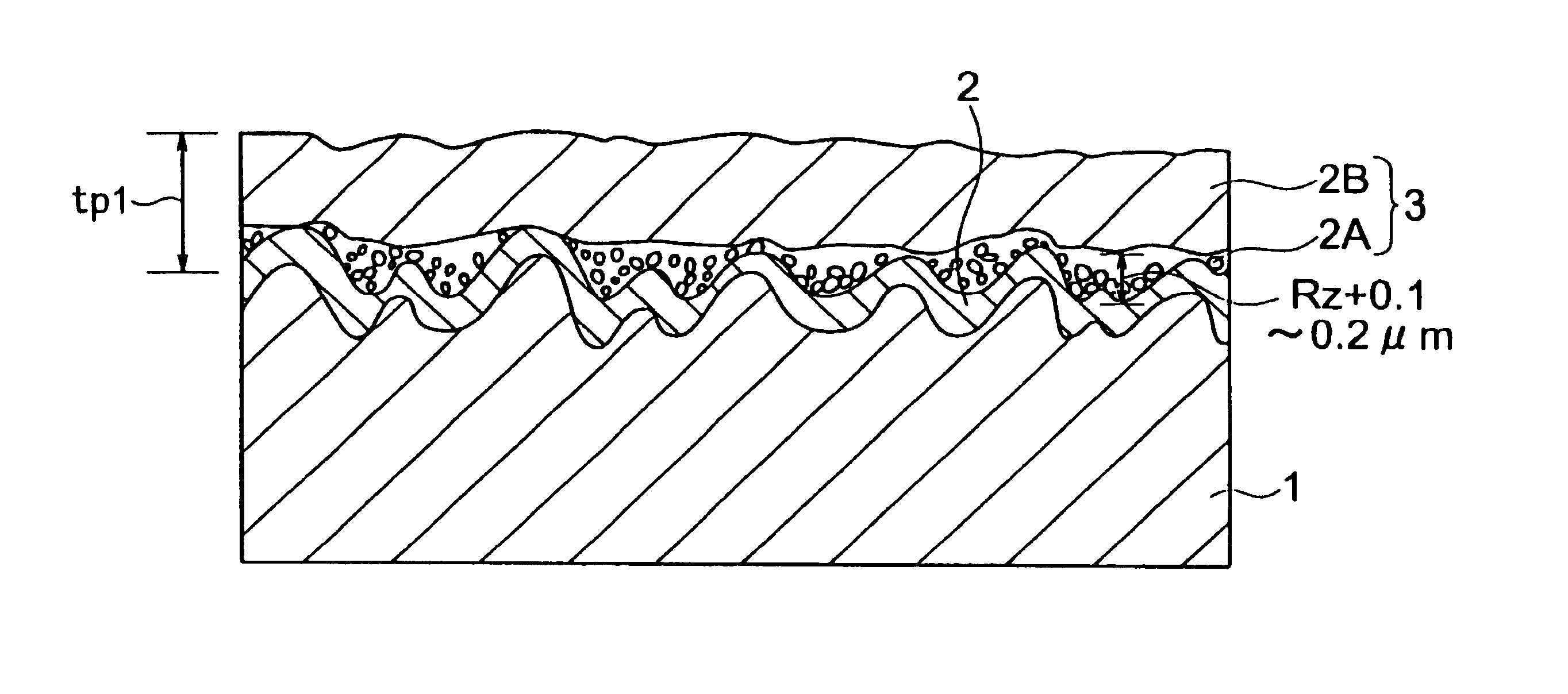
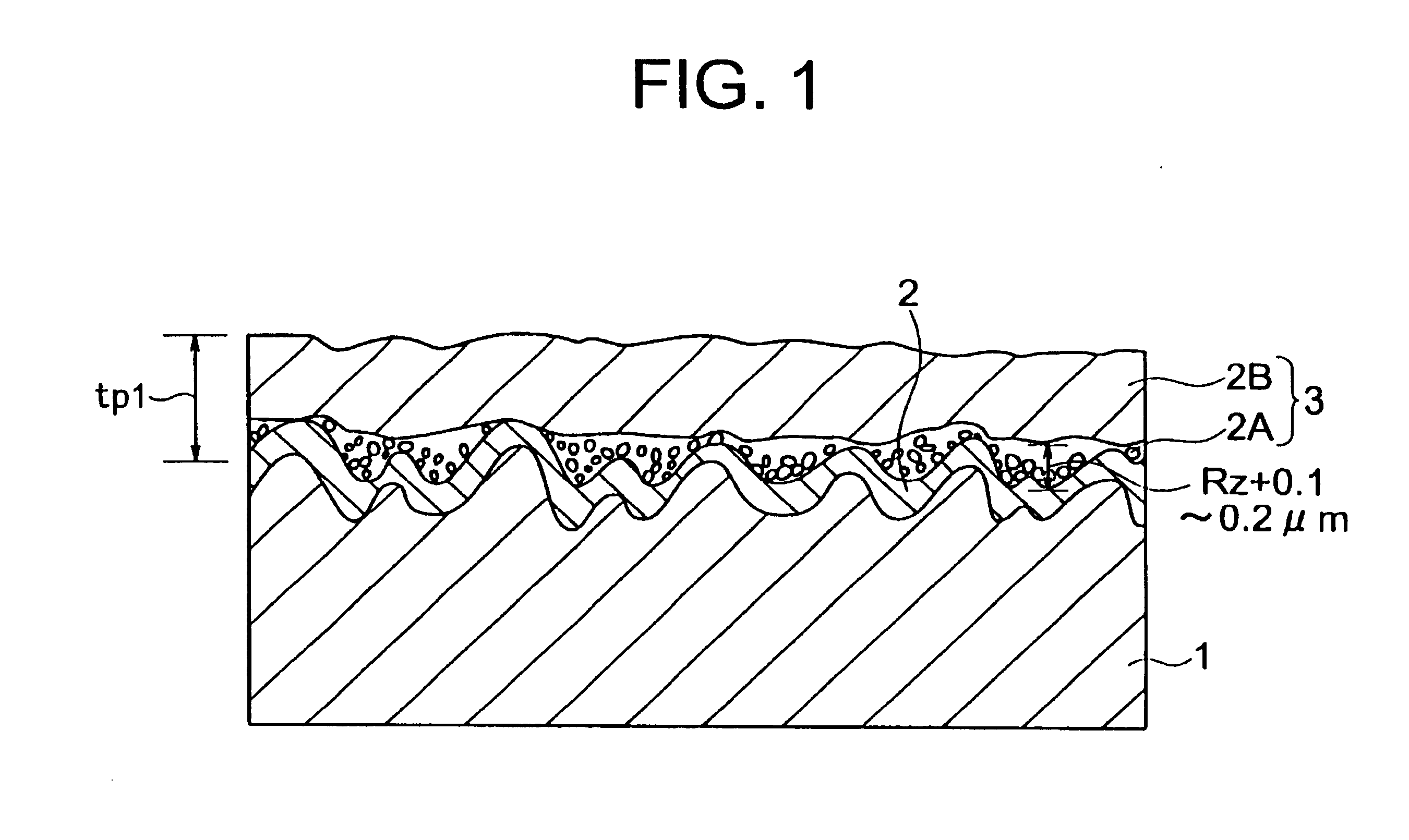
[0081]Preparation of carrier copper foil: As the carrier copper foil 1, an untreated electroplated copper foil having a thickness of 35 μm and a shiny surface roughness Rz of 4.1 μm was prepared. The peeling layer 2 and the ultra-thin copper 3 were formed under the same conditions as Example 3.

example 5

FIG. 2

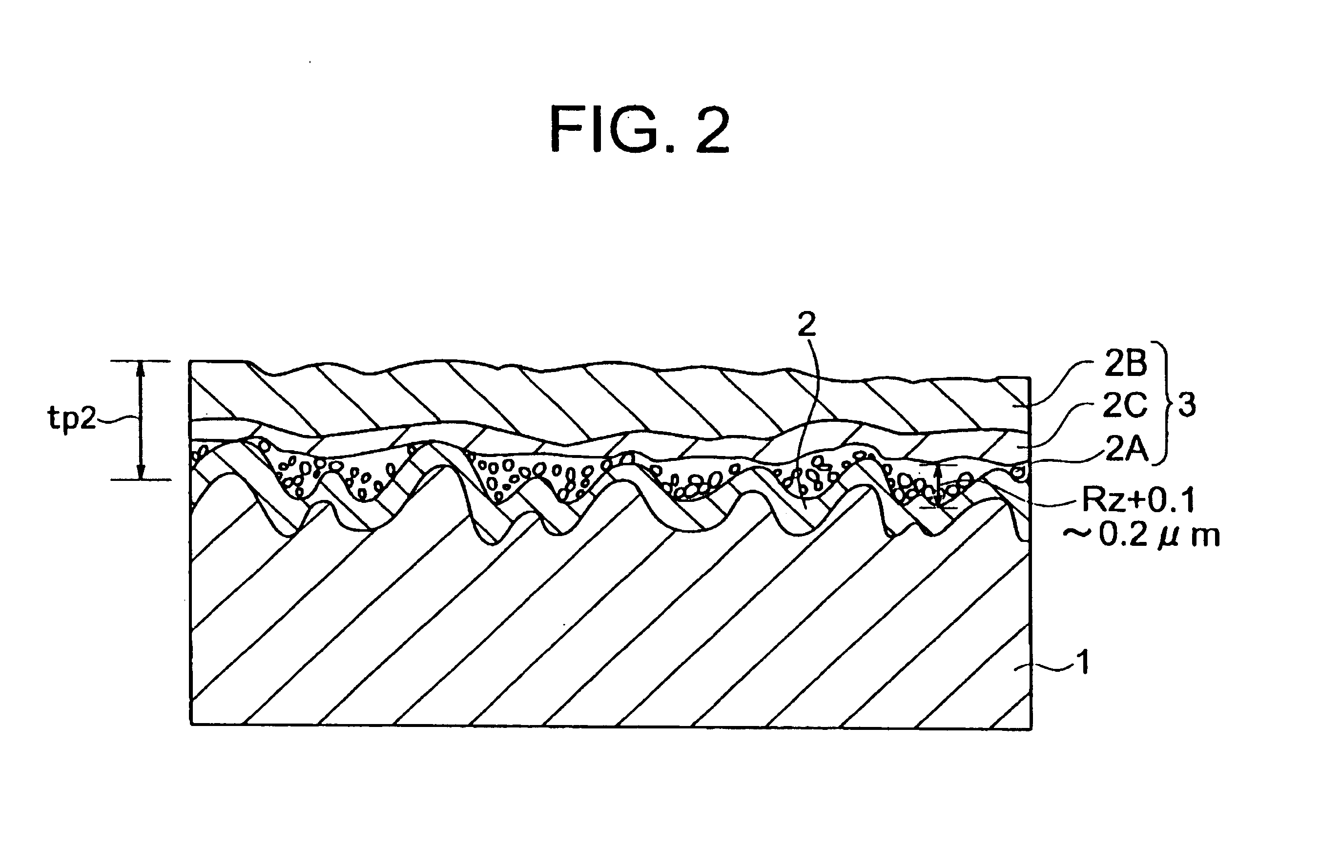
[0082]1. Preparation of carrier copper foil: As the carrier copper foil 1, an untreated electroplated copper foil having a thickness of 31 μm and a shiny surface roughness Rz of 1.1 μm was prepared.

[0083]2. Formation of peeling layer: The shiny surface of the carrier copper foil 1 was then treated by a dip method to form a peeling layer 2 comprised of metal chromium and an oxide hydrate film having an amount of deposition of metal of 0.014 mg / dm2.

[0084]3. Formation of phosphorus-containing layer at surface of peeling layer 2 and its vicinity: Next, this peeling layer 2 was strike plated for 60 seconds in a solution of:

[0085]

Cu2P2O7.3H2O: 20 g / literK4P2O7:300 g / literpH: 8

under conditions of a current density of 1.2 A / dm2 so as to form a phosphorus-containing layer 2A on the surface of the peeling layer 2 and its vicinity.

[0086]4. Formation of ultra-thin copper foil—1: Next, this phosphorus-containing strike plated layer 2A was formed with an ultra-thin copper layer 2C under con...

example 6

FIG. 2

[0091]1. Preparation of carrier copper foil: As the carrier copper foil 1, an untreated electroplated copper foil having a thickness of 31 μm and a shiny surface roughness Rz of 4 μm was prepared.

[0092]2. Formation of peeling layer: The shiny surface of the carrier copper foil 1 was then continuously electroplated with a nickel-chromium alloy to form a nickel-chromium alloy plating peeling layer 2 having an amount of deposition of 0.50 mg / dm2.

[0093]3. Formation of phosphorus-containing layer at surface of peeling layer 2 and its vicinity: Next, this nickel-chromium alloy peeling layer 2 was strike plated for 60 seconds in a solution of:

[0094]

Cu2P2O7.3H2O: 30 g / literK4P2O7:300 g / literpH: 8

under conditions of a current density of 1.5 A / dm2 so as to form a phosphorus-containing layer 2A on the surface of the peeling layer 2 and its vicinity.

[0095]4. Formation of ultra-thin copper foil—1: Next, this phosphorus-containing strike plated layer 2A was formed with a phosphorus-containi...


PUM

PropertyMeasurementUnit
Temperatureaaaaaaaaaa
Lengthaaaaaaaaaa
Lengthaaaaaaaaaa

Abstract

An ultra-thin copper foil with a carrier having a peeling layer able to withstand even high temperature working in the case of using a high heat resistant resin, enabling the carrier foil and the ultra-thin copper foil to be easily peeled apart, and reduced in the number of pinholes by uniform plating without impairing the peelability of the peeling layer, that is, an ultra-thin copper foil with a carrier comprised of a carrier foil, a peeling layer, and an ultra-thin copper foil, wherein the peeling layer and the ultra-thin copper foil are provided between them with a strike plating layer at the surface on the peeling layer side, an ultra-thin layer of copper is provided on this according to need, and an ultra-thin copper foil comprised of copper or a copper alloy or a phosphorus-containing copper or phosphorus-containing copper alloy is provided. The peeling layer between the carrier foil and the ultra-thin copper foil is chromium, a chromium alloy, a chromium-containing oxide hydrate layer, nickel, iron, or an alloy layer of the same or an oxide hydrate layer of the same.

Description

BACKGROUND OF THE INVENTION[0001]1. Field of the Invention[0002]The present invention relates to an ultra-thin copper foil with a carrier and a method of production of an ultra-thin copper foil with a carrier, more particularly relates to an ultra-thin copper foil with a carrier suitable for a printed circuit board for high density ultrafine interconnect (fine pattern) applications.[0003]2. Description of the Related Art[0004]A printed circuit board is produced as follows: First, an electrically insulating board comprised of a glass-epoxy resin, a glass polyimide resin, etc. is covered on its surface by a thin copper foil for formation of surface patterns, then the two are heated and pressed to produce a copper-clad laminate.[0005]Next, this copper-clad laminate is successively formed with through holes and plated at the through holes, then the copper foil at the surface of the copper-clad laminate is etched to form interconnect patterns of the desired line widths and line pitches. ...

Claims


Application Information

Patent Timeline
IPC IPC(8): C25D1/00C25D1/04C25D1/22C25D5/10H05K3/02H05K3/38H05K1/09
CPCC25D1/04C25D1/22C25D5/10H05K3/025H05K3/384Y10T428/12771Y10T428/12806Y10T428/12438Y10T428/1291Y10T428/12847Y10T428/12472Y10T428/12514Y10T428/12493C25D5/611H05K1/09
Inventor SUZUKI, YUUJIMATSUDA, AKIRA
Owner FURUKAWA ELECTRIC CO LTD
Why Eureka
Try Eureka