High speed digital radiographic inspection of piping

a digital radiographic inspection and high-speed technology, applied in material analysis using wave/particle radiation, instruments, nuclear engineering, etc., can solve problems such as structural fatigue and crack formation, difficult to obtain fast and accurate information about vessel defects, and substantial monetary costs and schedule delays

Inactive Publication Date: 2005-08-02
GENERAL ELECTRIC CO
View PDF13 Cites 46 Cited by
  • Summary
  • Abstract
  • Description
  • Claims
  • Application Information

AI Technical Summary

Problems solved by technology

In addition to manufacturing defects and other anomalies, such as obstructions, affecting fluid flow in the vessel, stresses imposed on the vessel in response to changes in fluid pressure can lead to structure fatigue and crack formation.
Frequently, companies must endure substantial monetary costs and schedule delays due to the detection and repair of these vessel anomalies.
As discussed in more detail below, the insulation layer tends to complicate the vessel inspection process, making it difficult to obtain fast and accurate information about vessel defects, such as corrosion under insulation, situated underneath the protective layer of insulation.
Accordingly, prior inspection methods have not been entirely satisfactory in detecting vessel defects, while minimizing inspection costs and scheduling delays.
This crawling device, typically referred to as a “pig”, poses a serious blockage to the normal fluid flow through a vessel and may require several days for the inspection of a lengthy vessel, decreasing vessel output capacity and production.
Furthermore, the amount of data a pig can record, the life of its battery, and the wear of its components from crawling the vessel all limit the usefulness of the pig.
Therefore, this technique typically fails to detect smaller-sized anomalies in a vessel and is relatively ineffective in pre-installation quality assurance testing.
It is important to note that the above mentioned ultrasonic inspection systems have not been entirely satisfactory with respect to the inspection of insulated vessels.
To avoid this unsatisfactory result, the system operator would be required to perform the costly and labor intensive step of removing the protective layer of insulation from the outer surface of the vessel prior to commencing the ultrasonic inspection process.
One of the disadvantages of this type of X-ray machine is that the wheels tend to climb the tangential sidewalls of the vessel, causing the carriage to rock or overturn while it is traveling through the vessel.
Such rocking motion also makes it difficult to properly align the attached radiation detector with the external radiation source as well as making it difficult to locate and position the radiation detector proximate the specific zone under inspection.
The failure to maintain proper alignment between the source and detector adversely impacts the quality and accuracy of the inspection data.
Moreover, as mentioned above, internal or invasive crawling devices pose a serious blockage to the normal fluid flow through a vessel, decreasing vessel output capacity and production.
However, the apparatus is not adapted to easily traverse past pipeline intersections, nor is the system capable of inspecting complex vessel structures such as heat exchangers, as discussed in more detail below.
Such systems typically require large amounts of film, and are relatively slow since the film must be removed and developed before the images can be examined.
As mentioned above, precise alignment has been heretofore difficult to achieve, especially given the immense size and length of vessels.
In view of the danger which radiation presents to the personnel handling the inspection equipment, digital or CMOS detectors are not entirely satisfactory for radiographic inspection systems.
For instance, digital or CMOS detectors are relatively insensitive or “hard of hearing”, therefore requiring the radiation source to emit relatively high levels of radiation for the generation of a detectable output signal.
On the other hand, for more complex inspection requirements, such as for the inspection of the internal structure of heat exchanger vessels, such two dimensional images have well-known limitations.
This makes it hard to study or inspect in great detail the independent characteristics of individual components or objects in the X-ray path.
Moreover, with standard X-ray techniques, one has a limited choice of viewing angles; thus, it is not feasible to obtain an elemental cross-sectional view of the vessel under inspection.
The technology has met with more limited application in industry, especially with respect to the inspection of heat exchanger and other fluid transport vessels.

Method used


Image

  • High speed digital radiographic inspection of piping
  • High speed digital radiographic inspection of piping
  • High speed digital radiographic inspection of piping

Examples


Embodiment Construction

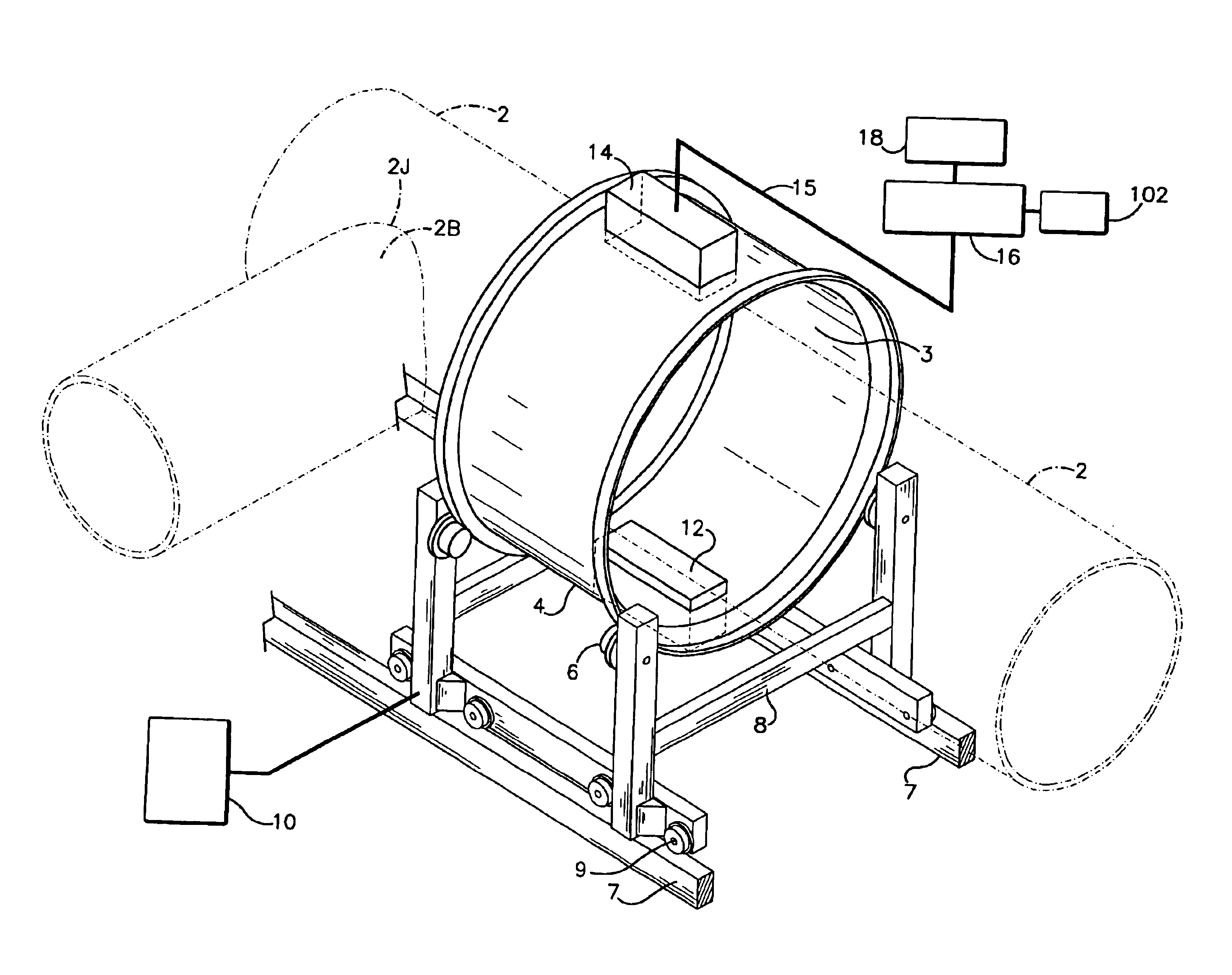
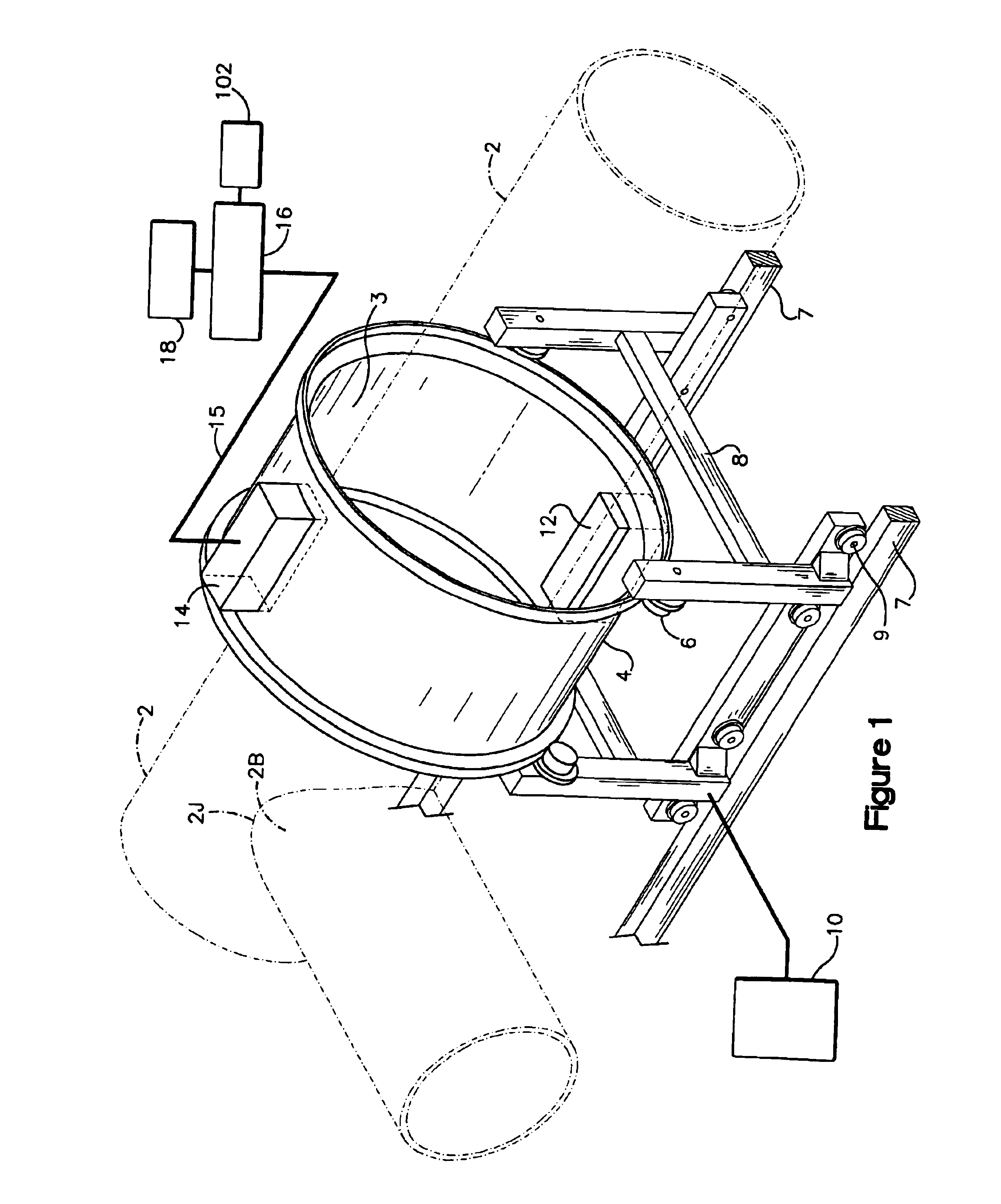
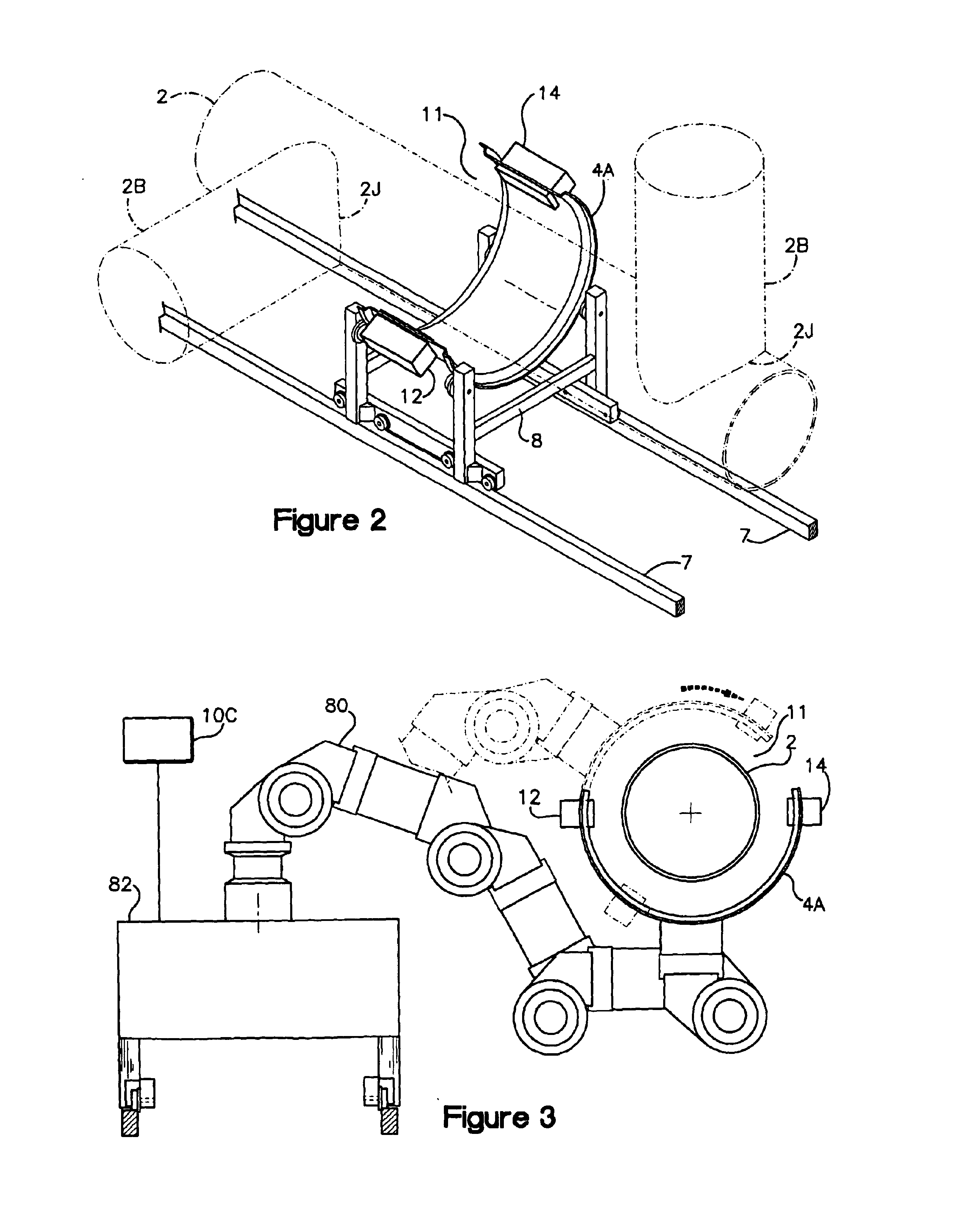
[0024]Referring to the drawings wherein identical reference numerals denote the same elements throughout the various views, FIG. 1 schematically shows a radiographic inspection system 100 for the inspection of fluid transport vessels 2. As mentioned above, the term vessel collectively includes, but is not limited to, a pipeline, pipeline section, column, column section, heat exchanger silo, and heat exchanger silo section; and, unless otherwise specified, aspects of the invention are applicable both to pre-installation quality assurance testing as well as to post-installation vessel fault, defect, and anomaly detection.

[0025]As best shown in FIG. 1, the inspection system 100 generally comprises a set of at least two carriage guide rails 7 positioned parallel to the longitudinal central axis of vessel 2. The system further comprises a carriage 8, slidingly mounted on a set of at least four carriage-rollers 9 which are rotably mounted on the guide rails 7, enabling the carriage to mov...


PUM

PropertyMeasurementUnit
speedaaaaaaaaaa
distanceaaaaaaaaaa
CTaaaaaaaaaa

Abstract

A system and method for high-speed radiographic inspection of fluid transport vessels in which a radiation source and a radiation detector are positioned on opposite sides of the outside surface of the vessel. A positioning system is provided for moving and locating the radiation source and radiation detector longitudinally with respect to the vessel and for moving the radiation source and radiation detector circumferentially with respect to the vessel. In operation, the positioning system causes the radiation source and radiation detector to spiral along the vessel in a coordinated manner while the radiation source illuminates an adjacent region of the vessel with radiation. The radiation is converted into corresponding electrical signals used to generate images of objects in the radiation path. Finally, an operator inspects the images for defects.

Description

FIELD OF THE INVENTION[0001]This invention relates generally to high-speed radiographic inspection of pipelines or other fluid transport vessels. Pipelines or vessels that transport fluid products such as natural gas, crude oil, and other chemical and petroleum products are subject to damage due to physical forces applied to them, and due to chemical and electrolytic action. To assure that a vessel is safe for continued operation it is periodically inspected for flaws by nondestructive testing or inspection apparatus.BACKGROUND OF THE INVENTION[0002]Throughout the following specification, the term vessel collectively includes, but is not limited to, a pipeline, pipeline section, column, column section, heat exchanger silo, and heat exchanger silo section; and, unless otherwise specified, aspects of the invention are applicable both to pre-installation quality assurance testing as well as to post-installation vessel fault, defect, and anomaly detection.[0003]In order to maintain subs...

Claims


Application Information

Patent Timeline
Patent Type & Authority Patents(United States)
IPC IPC(8): G01N23/04G01N23/02G01N23/18
CPCG01N23/04G01N23/18G01N23/083
Inventor BATZINGER, THOMAS J.LASIUK, BRIAN W.ALLISON, PETERMOHR, GREGORY A.MATULA, AUGUST D.
Owner GENERAL ELECTRIC CO
Why Eureka
Try Eureka