Supercharge Your Innovation With Domain-Expert AI Agents!

Electrical contacting element made of an elastic material

a technology of elastic materials and electric contacts, applied in the field of contact work, can solve the problems of easy damage to sensitive layers on the surface of work to be electroplated, affecting the process, and reducing the effect of mechanical loads and chemical attacks

Inactive Publication Date: 2005-08-09
ATOTECH DEUT GMBH
View PDF20 Cites 1 Cited by
  • Summary
  • Abstract
  • Description
  • Claims
  • Application Information

AI Technical Summary

Benefits of technology

The invention is about a new type of elastic contact material that is used in electrical contacts. This material is advantageous because it can compensate for any irregularities in the contact elements and the work being held, reducing the need for precise manufacturing. The elastic contact material is made up of a resiliently attached contact carrier and a contact element that is pressed against the work. The elastic material is made of a metal-plastic composite that contains metal particles and an elastic plastic. The fillers used in the composite can be very small, such as metal fibers or metal flakes. The elastic contact material has a slightly reduced conductivity compared to metals like titanium, but this is compensated by the fact that the contacts are more heated, resulting in better performance and durability. The elastic contact material can be manufactured with less precision in the contact elements and the work being held, which reduces costs.

Problems solved by technology

In said document, this embodiment is considered disadvantageous as the coating is complicated and expensive to manufacture and only lasts a short time in industrial utilization so that it often needs to be renewed.
The use of the reverse pulse current technique renders the process more difficult.
Under such extreme requirements, the known clamp contacts fail.
With the device described in DE 36 12 220 C2, by contrast, sensitive layers on the surface of work to be electroplated may easily be damaged.
As a result thereof, the conductive layer on the surface is interrupted which causes the current conducted from the clamp to the work to be hindered, or altogether interrupted.
If, moreover, boards of varied thickness are treated with the known device and are retained by the holding tongs for this purpose, the projections provided on the holding tongs possibly do not all touch the surfaces of the board in the same way so that in this case, the electric contact in which the board is placed is insufficient.
In this case, the surface is damaged and in case of thin electrically conductive surface layers like foils e.g., they can no longer be reliably placed in electric contact as a result thereof.
Under these conditions, high electroplating currents will burn the contact points.
In practical operation however, this proved impossible because of the technically necessary clearance in the driver pin and of the process tolerances always encountered.
Accordingly, the current density and, as a result thereof, the voltage drop on the contact resistance and the power loss on the small contact-making corner are extremely high.
In exceptional cases however, a burn through at the clamp may already occur at this layer thickness.
Again, this is only possible using an inherently elastic contact material.

Method used


Image

  • Electrical contacting element made of an elastic material
  • Electrical contacting element made of an elastic material
  • Electrical contacting element made of an elastic material

Examples


Embodiment Construction

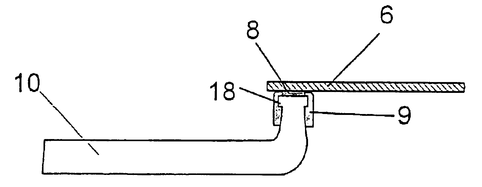
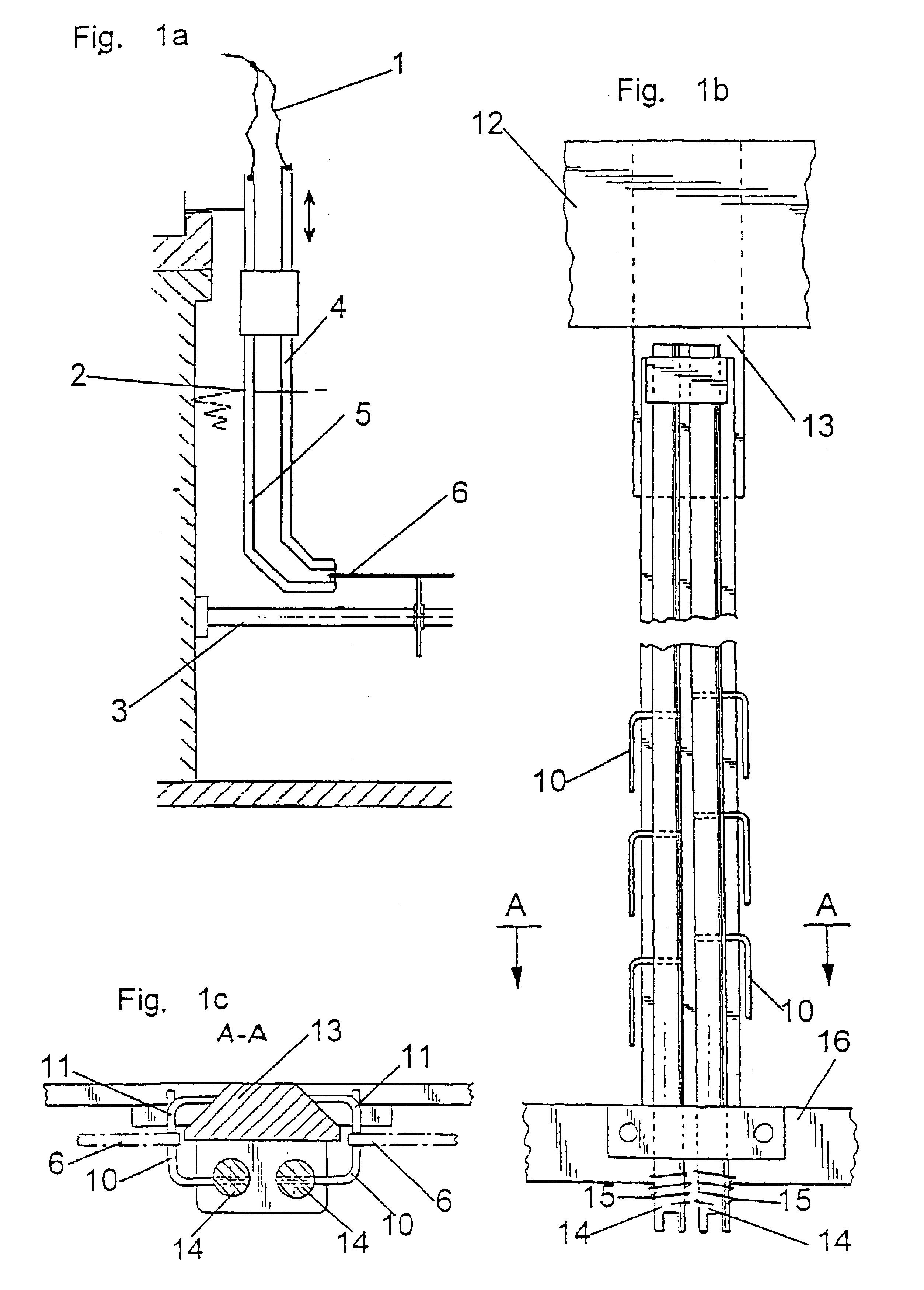
[0042]The FIGS. 1a-1c illustrate the general structure of holding and contacting facilities for work, more specifically for work to be electroplated. Accordingly, these Figs. concurrently represent the general structure of known facilities for holding work and for placing said work in electric contact, when they are not provided with the contact elements of the invention made of elastic, electrically conductive material.

[0043]FIG. 1a is a side view of an example of a clamp facility usually used for electroplating in horizontal continuous processing plants. By way of sliding contacts not illustrated herein, electric supply lines 1 connect the clamp facility to the electroplating current source (neither shown). The clamp, which consists of a stationary clamp arm 5 and of a spring mounted arm 4 is fastened by the stationary part 5 to a strap or a chain and endlessly revolves on a predetermined trajectory. At the beginning of the processing line in the continuous processing plant, after...


PUM

PropertyMeasurementUnit
thickaaaaaaaaaa
thicknessaaaaaaaaaa
current intensityaaaaaaaaaa

Abstract

To electrically contact and electrolytically treat, more specifically to electroplate, very thin, electrically conductive layers, especially with a high electrolytic current, a device comprising contact carriers, more specifically clamps, clips and like, with contact elements for supplying the current to the work is utilized, and at least the contact areas of the contact elements that may be brought to contact the work are made from an elastic, electrically conductive material.

Description

BACKGROUND OF THE INVENTION[0001]The invention relates to a device and to a method for contacting work that is to be subjected to electrolytic treatment, more specifically work to be electroplated, in electrolytic processes. This method includes but is not limited to electrolytic plating and electrolytic etching of printed circuit boards.[0002]The surface of the work to be electrolytically treated is electrically conductive. The surface of work which is made within of an electrically non-conductive material is usually only provided with a very thin metal layer that is highly sensitive to mechanical stresses and is electrolytically treated. During electroplating, said surface is cathodically polarized, i.e., the surface is connected to the negative pole of a direct current source. Accordingly, the counter electrode, an anode in this case, is connected to the positive pole so as to be electrically conductive. For electrolytic etching, the polarities are inverted. The work is then unde...

Claims


Application Information

Patent Timeline
Patent Type & Authority Patents(United States)
IPC IPC(8): C25D17/06C25D5/00H05K3/24C25D17/08
CPCC25D17/06C25D17/005H05K3/241
Inventor HUBEL, EGON
Owner ATOTECH DEUT GMBH
Features
  • R&D
  • Intellectual Property
  • Life Sciences
  • Materials
  • Tech Scout
  • Unparalleled Data Quality
  • Higher Quality Content
  • 60% Fewer Hallucinations
Learn More