
Partially treated water-repellent glass sheet

a technology of water-repellent glass and glass panes, which is applied in the field of partially treating water-repellent glass sheets, can solve the problems of increasing the cost of water-repellent film processing, the inability of the holders to be attached to the water-repellent glass panes, and the inability to achieve the required adhesive strength between the adhesive and the glass pane, so as to achieve the effect of reducing production costs and increasing productivity

Inactive Publication Date: 2005-08-09
NIPPON SHEET GLASS CO LTD
View PDF6 Cites 27 Cited by
  • Summary
  • Abstract
  • Description
  • Claims
  • Application Information

AI Technical Summary

Benefits of technology

[0020]Another object of the present invention is to provide a water-repellent sheet of glass free from the foregoing optical inconveniences.
[0032]The undercoat may be formed by a sol-gel process which enables film forming at a low-temperature atmosphere. This leads to increased productivity and hence reduction in the cost of production.

Problems solved by technology

However, a problem is encountered in connecting the holders to a water-repellent pane of glass by means of an adhesive.
More specifically, it is impossible to achieve a required adhesive strength between the adhesive and the glass pane because the water-repellent film of the water-repellent pane of glass functions to repel the adhesive.
As a consequence, the holders cannot be attached to the water-repellent glass pane.
However, in the abrasive method, it is difficult and laborious to partially remove the water-repellent film by means of abrasives, thereby increasing the cost of processing of the water-repellent film.
Again, in the masking tape method, it is troublesome and laborious to apply masking tapes to the glass pane and to peel off the tapes from the glass pane.
Further, it is quite difficult to achieve minute masking on the glass pane.
Thus, the masking tape method is not effective for a curved pane of glass.
It is quite tedious to make the relevant control follow those changes.
Thus, it is liable to happen that an incident ray 107 originating from a source of light such as light of a car running on an opposite lane is reflected by the edges 106 to thereby cause mis-detection of the rain sensor 103.
The abrasive method and the masking tape method are therefore not suited to form the window-shaped non-repellent part 105 in front of the sensor.

Method used


Image

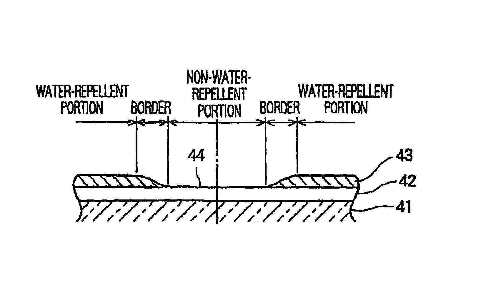
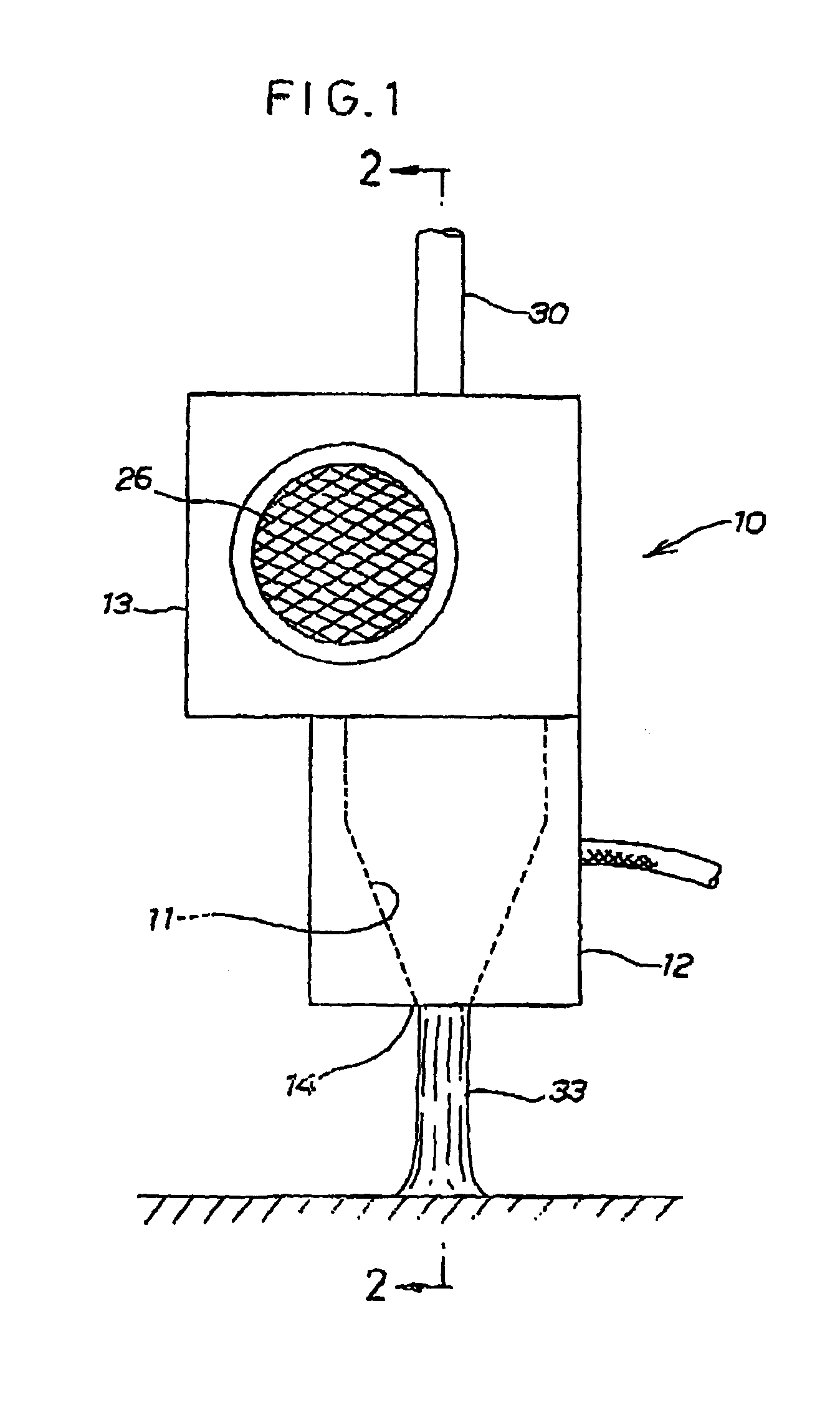
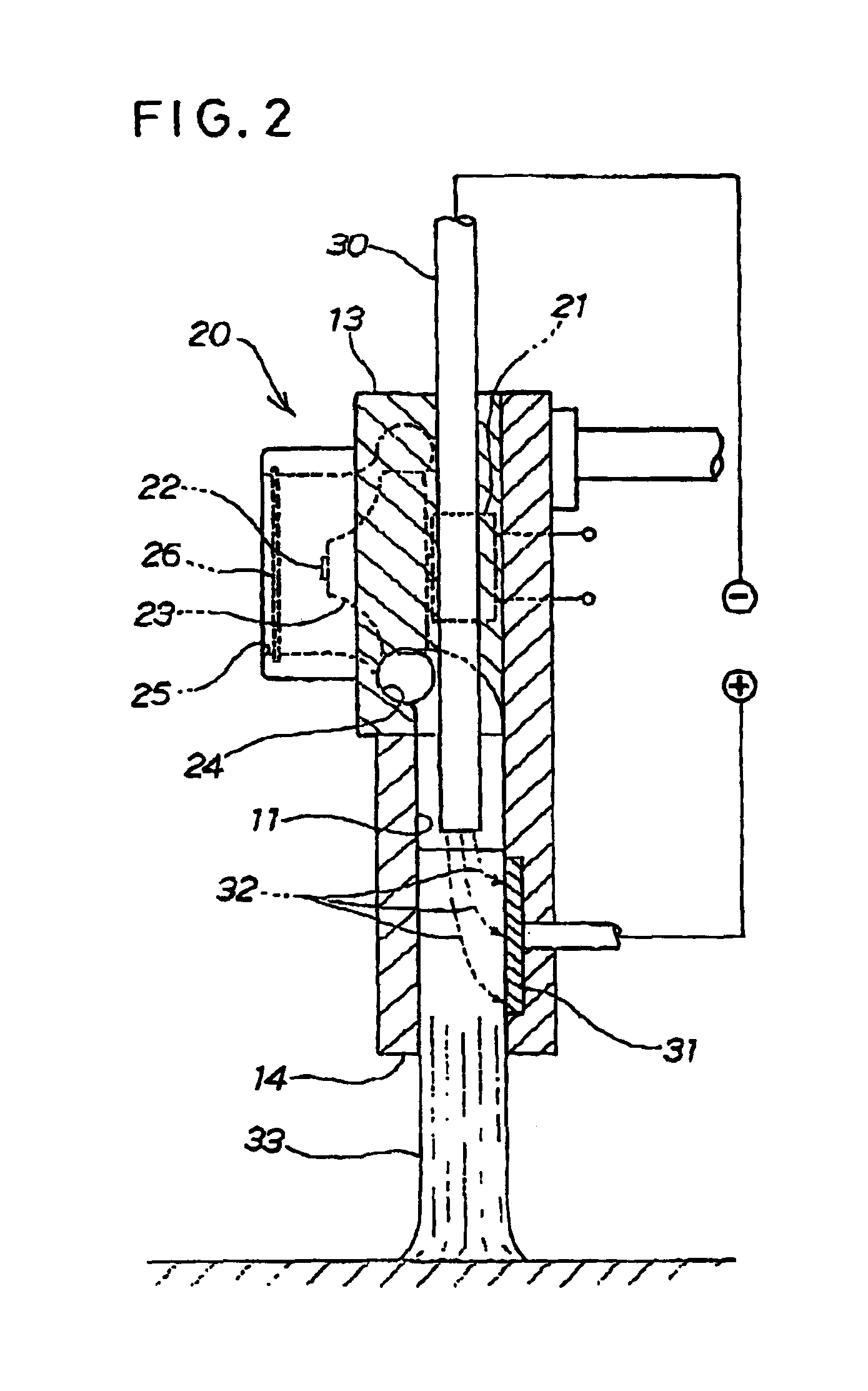
  • Partially treated water-repellent glass sheet
  • Partially treated water-repellent glass sheet
  • Partially treated water-repellent glass sheet

Examples


example 1

[0057]EXPERIMENTAL EQUIPMENT: APPARATUS FOR TREATING FORMED PRODUCT WITH PLASMA JETS (available from COROTEC Corp.)[0058]SAMPLE: water-repellent glass sheet (including an undercoat of SiO2 having a thickness or 40 nm, and a water-repellent film of perfluoroalkylsilane having a thickness of 4 nm)[0059]DISTANCE H: 10 mm (See FIG. 3A)[0060]POWER: 0.5 kW for each plasma jet irradiation gun[0061]STRIKING VELOCITY OF PLASMA JETS (rate at which plasma jets impact upon a sample): about 7 m / s[0062]VELOCITY OF PLASMA JET IRRADIATION GUN (in movement parallel to the water-repellent glass sheet surface); 100 mm / sec[0063]TREATMENT: two times[0064]CONVERSION VELOCITY: 50 mm / sec[0065]EVALUATION: contact angle

[0066]FIG. 6 is a graph showing contact angles obtained from EXAMPLE 1. A horizontal axis shows the distance L (See FIG. 3B) from the center of the surface of the water-repellent glass sheet irradiated with plasma jets. A vertical axis shows contact angles θ. A contact angle θ is given between...

examples 2 to 4

[0068]EXPERIMENTAL EQUIPMENT: APPARATUS FOR TREATING FORMED PRODUCT WITH PLASMA JETS (available from COROTEC Corp.)[0069]SAMPLE: water-repellent glass sheet (including an undercoat of SiO2 having a thickness of 30 to 40 nm, and a water-repellent film or perfluoroalkylsilane having a thickness of 2 to 5 nm)[0070]DISTANCE H: 10 nm[0071]POWER: 0.5 kW for each plasma jet irradiation gun[0072]STRIKING VELOCITY OF PLASMA JET: about 7 m / s[0073]VELOCITY OF PLASMA JET IRRADIATION GM: 100, 20, and 120 nm / sec[0074]TREATMENT: four times or once

[0075]

TABLE 1EXAMPLEEXAMPLEEXAMPLEEXAMPLE1234DISTANCE H 10 mm 10 mm10 mm 10 mmVELOCITY100 mm / sec100 nm / sec10 mm / sec120 mm / secOF PLASMAJET IRRA-DIATIONGUNTREATMENTtwicefour timesonceonceCON- 50 mm / sec 25 mm / sec10 mm / sec120 mm / seeVERSIONVELOCITYEVAL-goodgoodgoodno goodUATION

[0076]CONVERSION⁢ ⁢VELOCITY=VELOCITY⁢ ⁢OF⁢ ⁢THE⁢ ⁢PLASMA⁢ ⁢JET⁢ ⁢IRRADIATION⁢ ⁢GUNNUMBER⁢ ⁢OF⁢ ⁢TIMES⁢ ⁢SAMPLE⁢ ⁢IS⁢ ⁢TREATED

[0077]In EXAMPLE 2, the velocity of the plasma jet irradiatio...

examples 5 to 7

[0084]EXPERIMENTAL EQUIPMENT: APPARATUS FOR TREATING FORMED PRODUCT WITH PLASMA JET (available from COROTEC Corp.)[0085]SAMPLE: water-repellent glass sheet (including an undercoat of SiO2 having a thickness of 30 to 40 nm, and a water-repellant film of perfluoroalkylsilane having a thickness of 2 to 5 nm) or a conventional glass sheet[0086]DISTANCE H: 10 mm[0087]POWER: 0.5 kW for each plasma jet irradiation gun[0088]STRIKING VELOCITY OF PLASMA JET: about 7 m / s[0089]VELOCITY OF PLASMA JET IRRADIATION GUN: 40 mm / sec[0090]TREATMENT: twice[0091]CONVERSION VELOCITY: 20 mm / sec

[0092]

TABLE 2EXAMPLEEXAMPLEEXAMPLE567Distance H10 mm10 mm10 mmVelocity of PlasmJet40 mm / s40 mm / s40 mm / sIrradiation GunTreatmenttwicetwicetwiceConversion Velocity20 mm / s20 mm / s20 mm / sTested Portionnon-water-water-surface ofrepellentrepellentconventionalportionportionglass sheetAdhesive Strength Fx80 kgf059 kgfAdhesive Strength FZ10 kg or010 kg or moremoreFailurecohesiveinterfacial failurecohesive failurefailure

[0093]I...


PUM

PropertyMeasurementUnit
velocityaaaaaaaaaa
distanceaaaaaaaaaa
distanceaaaaaaaaaa

Abstract

A method for partially treating a water-repellent glass sheet is disclosed which comprises irradiating part of a water-repellent glass film, formed on the water-repellent glass sheet, with a stream of plasma jets generated by a plasma jet irradiating gun. By such plasma jet irradiation, the film part can be removed easily even when the glass sheet has a curved surface. A water-repellent glass sheet with the film part removed is also disclosed.

Description

[0001]This application is a divisional of application Ser. No. 10 / 048,832, filed Jan. 29, 2002, now U.S. Pat. No. 6,685,992, which application(s) are incorporated herein by reference.TECHNICAL FIELD[0002]The present invention relates to a method for partially treating a water-repellent glass sheet to remove part of a water-repellent function of the glass sheet. The invention also relates to a water-repellent glass sheet with part of its water-repellent film removed.BACKGROUND ART[0003]In recent years, water-repellent glass sheets are widely used on vehicles so as to repel rain drops from fields of view of drivers of the vehicles to thereby ensure safety driving in a rainy weather.[0004]Such glass sheets are known from, for example, Japanese Patent Laid-Open Publication Nos. HEI-4-130032 and HEI-4-305037. The glass sheet disclosed in Japanese Patent Laid-Open Publication No. HEI-4-130032 includes a glass substrate, a film of SiO2 (silicon dioxide) formed on the glass substrate, and a...

Claims


Application Information

Patent Timeline
Patent Type & Authority Patents(United States)
IPC IPC(8): B32B3/00H05H1/24C03C17/30B60J1/20C03C17/42C03C23/00
CPCC03C17/30C03C17/42C03C23/006C03C2217/76C03C2218/328Y10T428/24777Y10T428/24488Y10T428/2495Y10T428/24612Y10T428/24942Y10S428/913
Inventor OGAWA, HISASHIYAMAMOTO, HIROAKITERANISHI, TOYOYUKIKOBAYASHI, HIROAKIKURAMOTO, SHUNJI
Owner NIPPON SHEET GLASS CO LTD
Learn More