Optical detection system, device, and method utilizing optical matching

a detection system and optical matching technology, applied in the field of pointing devices, can solve the problems of inability to accurately manipulate the cursor, inability to accurately detect the position of the cursor, and many other problems, and achieve the effects of reducing the processing power necessary, reducing the effect of lateral motion from the other direction, and producing little change in the image data signal

Inactive Publication Date: 2005-08-09
LOGITECH EURO SA
View PDF52 Cites 68 Cited by
  • Summary
  • Abstract
  • Description
  • Claims
  • Application Information

AI Technical Summary

Benefits of technology

[0026]One cross-correlation analysis can occur when there is a multi-resolution image scheme. In particular, the cross-correlation analysis between the new speckle image data signal and the previous speckle image data signal is computed over a limited set of points. In particular, this set of points is all points in a low resolution image area plus a small range of points around the estimated displacement in a high resolution image area. The displacement related to the movement is determined by where a cross-correlation function of the cross-correlation analysis peaks. Using and applying the cross-correlation analysis over a limited set of points significantly reduces the processing power necessary to achieve a desired precision of determining displacement, or movement, of the optical pointing device.
[0027]Another cross-correlation analysis can occur where there is a single resolution image scheme. In particular, the cross-correlation analysis between the new speckle image data signal and a reference, or previous, speckle image data signal is computed in one dimension—along a direction perpendicular to the elongated speckle images. The effects of lateral motion from the other direction is minimized because the speckles are elongated in that direction, therefore, producing little change in the image data signal as long as lateral displacement is smaller than the largest dimension of a pixel of a photosensor array. The one-dimensional cross-correlation analysis reduces power consumption because fewer calculations are required to determine displacement of the optical pointing device.
[0030]The claimed invention advantageously provides an optical detection system that detects movement of an optical pointing device relative to a surface that can generate speckle images. The claimed invention includes an optical sensing assembly having one or more optical elements and one or more artificially limited apertures that are optically matched to a plurality of photosensor arrays that generate an unambiguous image data signal from a speckle image formed from a diffusely scattered coherent light beam. The unambiguous image data signal is used to detect movements with greater precision without requiring greater system resources such as computational power and / or illumination power. Further, the claimed invention overcomes the adverse affects of position tolerance by allocating additional identical optical elements for each photosensor array so that the overlapping images of the illumination spot are generated to adequately cover each photosensor array even with worst case misalignment considerations.

Problems solved by technology

The electromechanical mouse, however, has drawbacks associated with many other devices that have mechanical parts.
Namely, over time the mechanical components wear out, become dirty, or simply break down so that the cursor can no longer be accurately manipulated, if at all.
One problem with the conventional optical mouse is that it requires an optical pad as described above.
The use of a coherent light source, however, produced more problems.
The first problem the conventional coherent light optical mouse incurs is from the use of coherent light and speckles.
A pattern is improperly detected by an imaging device when it is too small.
For commercially available coherent light sources (λ=0.6 to 0.96 micrometers), imaging such a small pattern is currently not achievable at full resolution with current semiconductor technology.
Thus, ambiguous and hard to interpret data is read from the sensor when a speckle is smaller than the imaging resolution.
This, in turn, leads to erroneous displacement estimates that adversely affect system performance by producing an erroneous displacement sign value.
Thus, attempts by conventional optical systems to solve position tolerance, i.e., misalignment, were accompanied by a loss of reflected light that can be captured by the photosensor array.
Another problem with conventional optical pointing devices based on speckle image analysis is sensitivity of an estimation scheme to statistical fluctuations.
Therefore, it is unavoidable for the system to be locally subjected to ambiguous or hard to interpret data, such as where a speckle count observed by the imaging system is small.
An additional problem in conventional optical pointing devices is attaining a small displacement resolution without significantly increasing costs due to increased hardware complexities and increased computational loads.
For even higher displacement resolutions, sub-pixel displacement can be obtained through interpolation by a factor I, however with an excessive increase of computations.
Such large computational load required costly and power hungry digital hardware which is difficult to integrate in a small hand held pointing device.
One more problem with conventional optical pointing devices based on cross-correlation detection is that they are insensitive to displacement occurring when the pointing device speed is lower than the image resolution divided by (mag*T_acq), that is for a displacement smaller than a pixel.

Method used


Image

  • Optical detection system, device, and method utilizing optical matching
  • Optical detection system, device, and method utilizing optical matching
  • Optical detection system, device, and method utilizing optical matching

Examples


Embodiment Construction

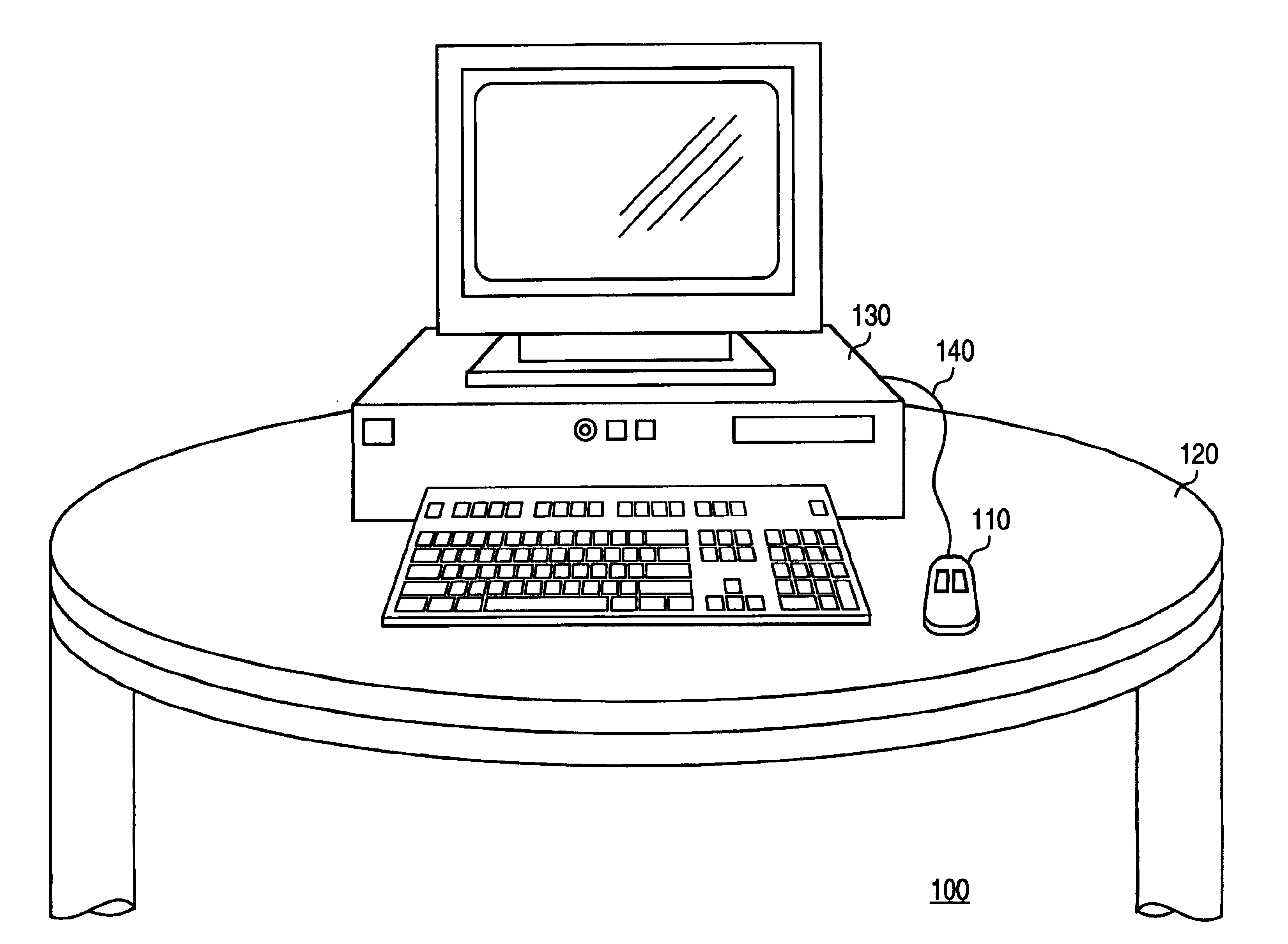
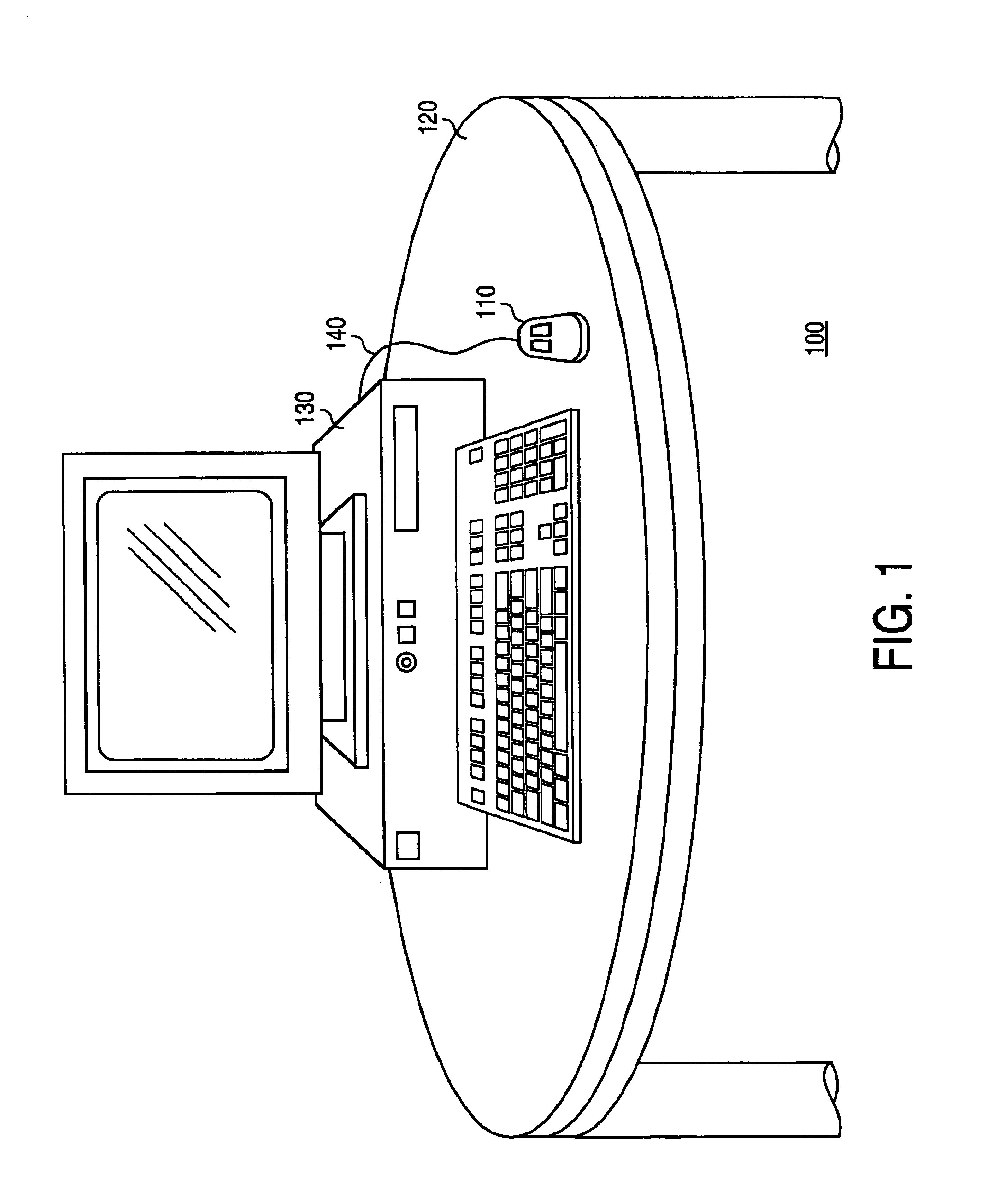
[0047]FIG. 1 is a diagram of an embodiment of an operating environment 100 in accordance with the present invention. The operating environment 100 includes an optical pointing device 110, a surface 120, and a computer system 130. The surface 120 may be any surface that can diffusely reflect light, such as a table or desk, for example. The computer system 130 may be a conventional computer system such as an IBM PCT™, Apple MacIntosh™. Sun SPARCStation™, or the like. The computer system 130 includes a processor, a memory, a display screen, and an input port for a pointing device. The optical pointing device 110 is coupled to the input port of the computer system 130. It is noted that although the optical pointing device 110 may be coupled to the input port of the computer system 130 using a wire connection such as an optical pointing device cable 140, other coupling connections such as infrared or radio frequency control may also be applicable.

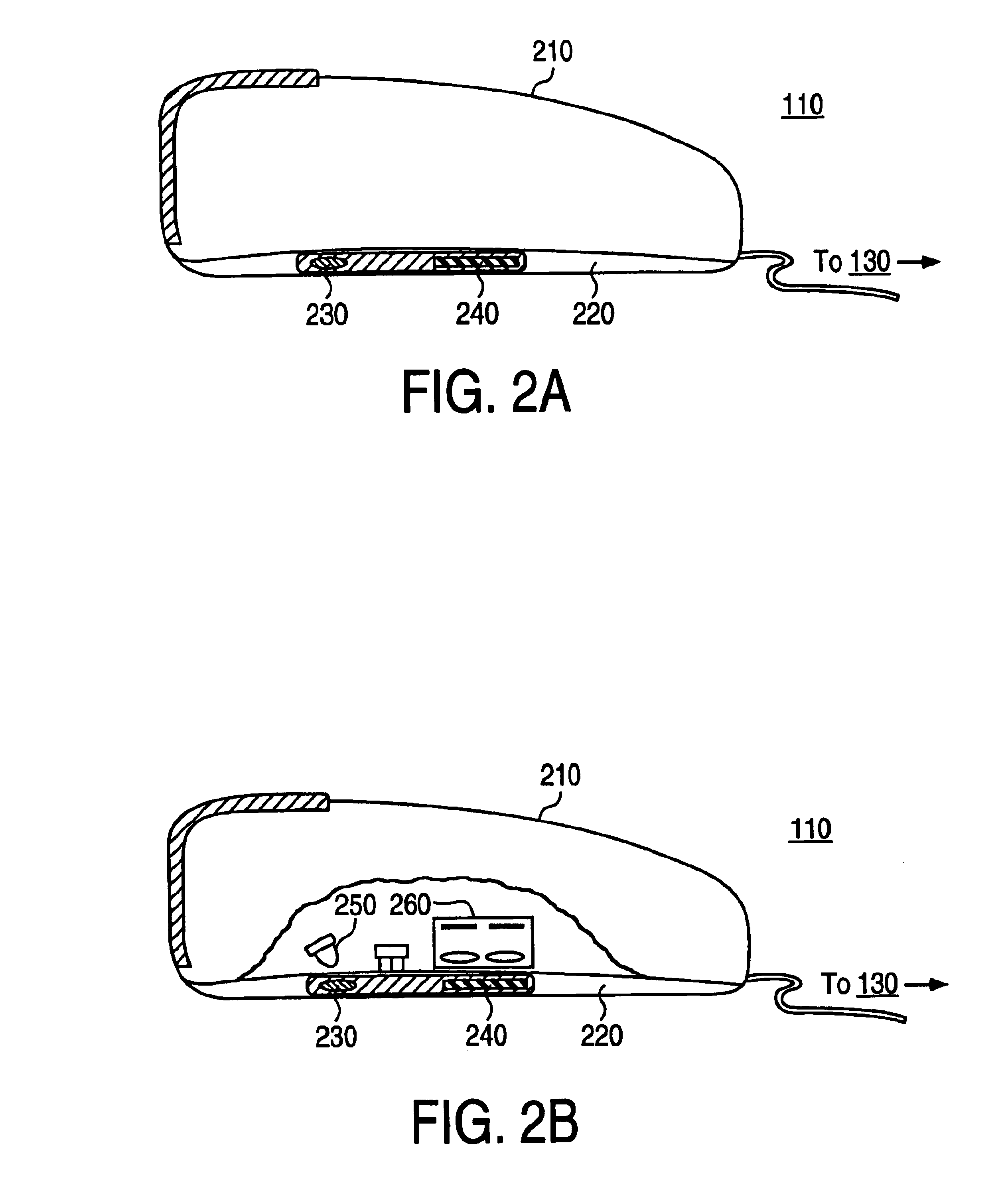
[0048]FIG. 2a is an external diagram of t...


PUM


Abstract

An optical detection system and method detects movement of an optical pointing device in a data processing environment. The system works with any surface than can diffusely scatter a collimated beam from a coherent light source. Specifically, the system comprises a coherent light source and an optical sensing assembly. The optical sensing assembly comprises a plurality of photosensor arrays and a plurality of optical elements. Each photosensor array includes pixels of a particular size and shape. Each optical element has an artificially limited aperture and is associated, through optical matching, with a respective photosensor array. The coherent light source generates a collimated beam that is diffusely reflected off of the surface. The optical sensing assembly receives the diffusely reflected, or scattered, collimated beam and passes it through the artificially limited apertures of the optical elements to the associated corresponding photosensor array. Passing the scattered light through the optical elements generates speckle images that appear on the pixels, of the photosensor arrays. Based on the pixel shape, a pixel value associated with the speckle image provides a speckle image data signal. When there is translation of the pointing device, a new set of speckle images, each reassembling to a translated version of the previous speckle image, are generated and another speckle image data signal is generated. The new and the previous speckle image data signals are then used in a motion detection analysis to determine the points of the two data signals that give a displacement value.

Description

CROSS-REFERENCE TO RELATED APPLICATION[0001]This application is a continuation of U.S. patent application Ser. No. 08 / 869,471, filed Jun. 5, 1997, now U.S. Pat. No. 6,256,016.BACKGROUND OF THE INVENTION[0002]1. Field of the Invention[0003]The present invention relates to pointing devices for cursors on video display screens in a data processing environment. More particularly, the present invention relates to an optical system, device, and method for imaging a surface to perceive a displacement of the surface without having mechanically moving parts or without requiring a specially patterned surface.[0004]2. Description of the Related Art[0005]Pointing devices, such as a mouse or a trackball, are well known peripheral devices in data processing environments. Pointing devices allow for cursor manipulation on a visual display screen of a personal computer or workstation, for example. Cursor manipulation includes actions such as rapid relocation of a cursor from one area of the display ...

Claims


Application Information

Patent Timeline
Patent Type & Authority Patents(United States)
IPC IPC(8): G06F3/033G06F3/03
CPCG06F3/0317
Inventor PIOT, JULIENSCHNELL, URBAN G.NUSSBAUM, PHILIPPE J.
Owner LOGITECH EURO SA
Why Eureka
Try Eureka