
System and method for interference mitigation using adaptive forward error correction in a wireless RF data transmission system

Inactive Publication Date: 2005-08-09
NETGEAR INC
View PDF4 Cites 70 Cited by
  • Summary
  • Abstract
  • Description
  • Claims
  • Application Information

AI Technical Summary

Benefits of technology

[0014]The present invention is directed to a system and method of varying forward error correction (FEC) parameters on an RF data link which connects from one data transmission station such as a hub station transmitter to a number of other data transmission stations such as subscriber station receivers. This variation of FEC parameters improves the availability and capacity of an RF data link as compared to the same RF data link with fixed FEC parameters. A link being a connection between hub station and one or a plurality of subscriber stations, or being a connection between one or a plurality of subscriber stations and a hub station. A link may also be a connection between a hub station and one or a plurality of subscriber stations over any media, such as a wireline or a point to point RF link. The FEC parameters adjusted set the mixture of overhead and data on the RF data link. The FEC parameters are adjusted in response to interference and signal strength changes present at the subscriber station receiver.

Problems solved by technology

A fundamental problem with protected, regulated RF transmission systems is that only a few such systems can operate in any given geographic area due to the limited RF frequency spectrum allocated to data access services.
Interference between the multiplicity of RF transmissions using the U-NII spectrum allocations at the same time in a given geographic area causes degradation in the quality of high-capacity data access in that area.
However, if too much information content reduction is performed, the data rate for end-users who require little information content reduction will be slower than optimal, and the average data rate of the downstream signals will be reduced below optimal.
However, each subscriber is forced to use only the limited capacity available through the available bandwidth slices.
Also, in point-to-multipoint systems using unprotected, regulated RF spectrum it is likely that interference will vary greatly and suddenly over time.
Hence, an interference mitigation system which results in end-user coverage normally considered adequate may suddenly result in reduced end-user coverage.

Method used


Image

  • System and method for interference mitigation using adaptive forward error correction in a wireless RF data transmission system
  • System and method for interference mitigation using adaptive forward error correction in a wireless RF data transmission system
  • System and method for interference mitigation using adaptive forward error correction in a wireless RF data transmission system

Examples


Embodiment Construction

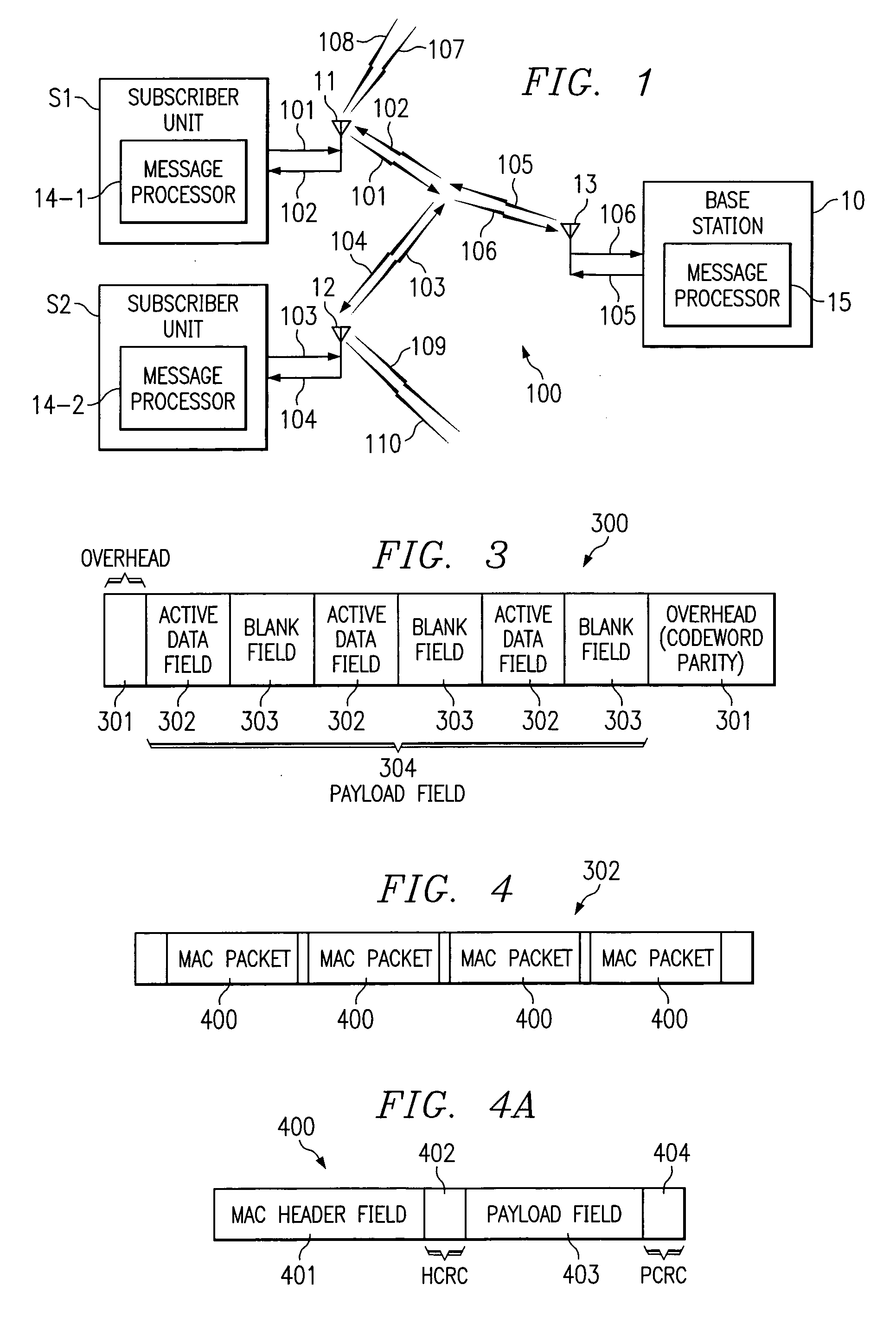
[0032]Turning now to FIG. 1, there is shown system 100, which includes a plurality of subscriber stations S1, S2 connected via antennas 11, 12 and 13 to hub base station 10 over an RF interface shown as signals 101, 102, 103, 104, 105 and 106. The system may experience interference such as from noise sources 107, 108, 109 and 110. Signals 102 and 104 are preferably different linearly filtered versions of signal 105. Noise sources 108 and 110 are added to signals 102 and 104 respectively. Similarly, signal 106 is the sum of linearly filtered signals 101 and 103 and noise sources 107 and 109. Included in the subscriber stations are message processors 14-1 and 14-2 respectively, and included in base station 10 is message processor 15. Preferably the hub base station and the subscriber stations exchange FEC encoded data adapted by the present invention.

[0033]The downstream FEC encoder is contained within the base station message processor 15, and a downstream FEC decoder is defined with...


PUM


Abstract

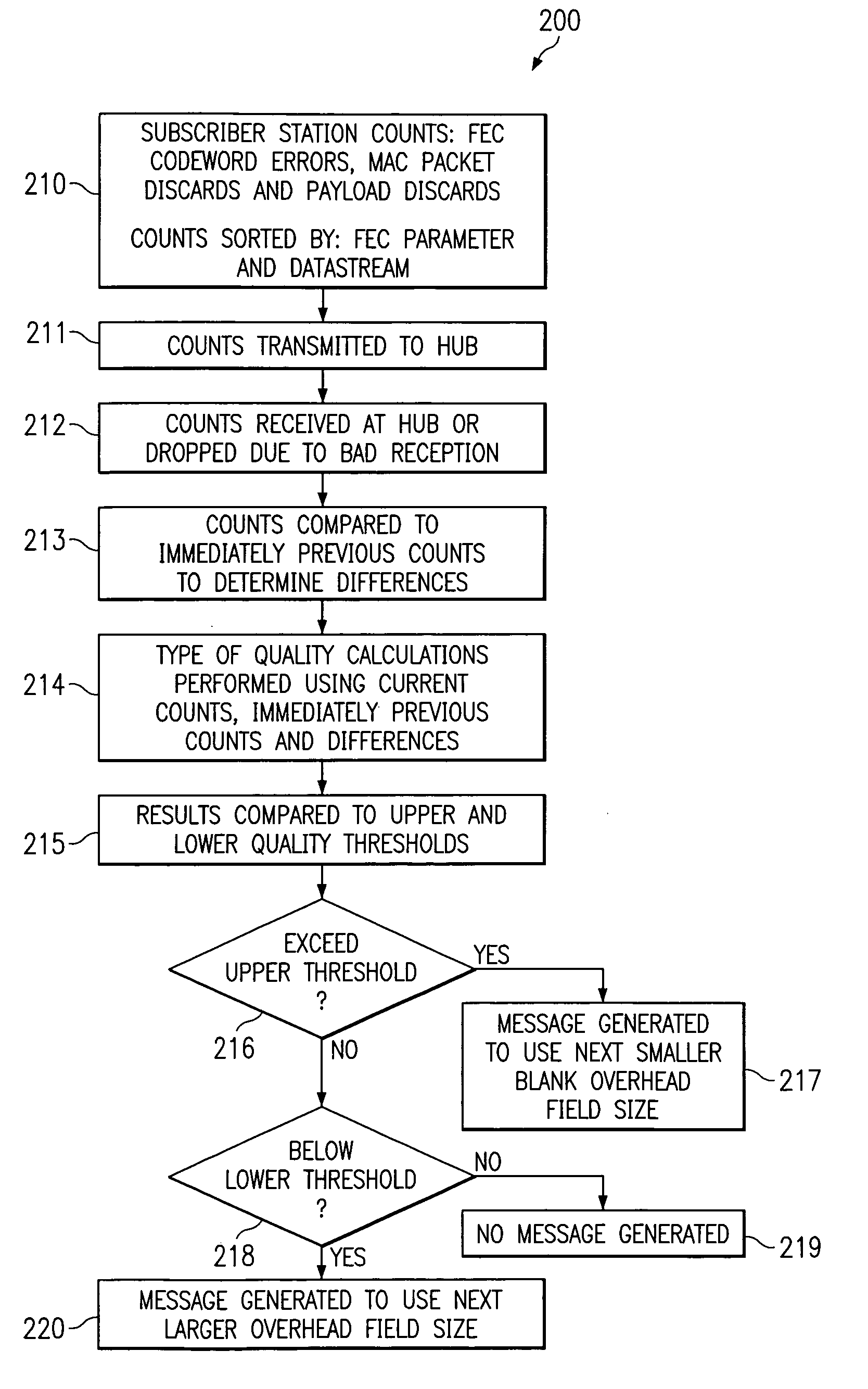
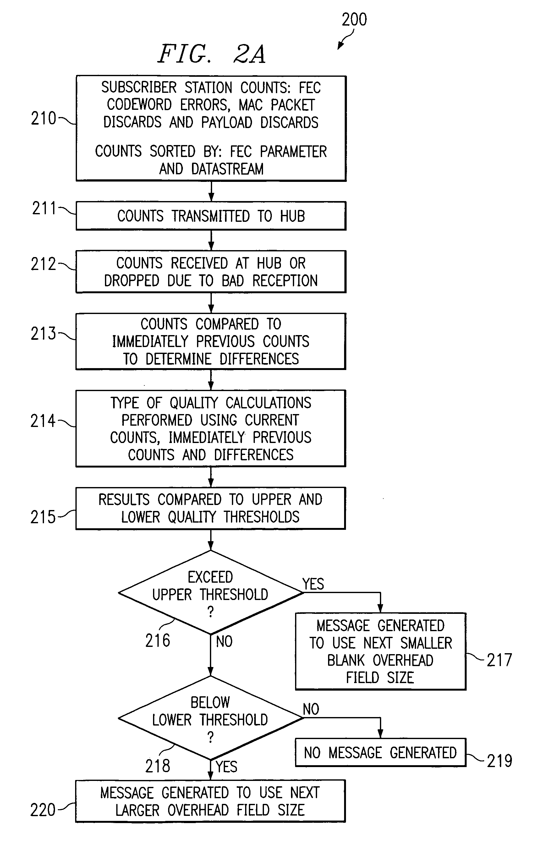
An adaptive forward error correction system for mitigating interference and fading in RF data transmissions has a hub and subscriber stations transmitting and receiving forward error correction encoded data packets. The hub and subscriber stations count codewords and / or packets received with errors. The hub calculates a type of quality measure using the counts and compares this measure to quality thresholds. If an upper threshold is exceeded, the hub increases a size of transmitted active data fields and decreases a size of blank data fields. If a lower threshold is not met, the hub decreases a size of transmitted active data fields and increases a size of blank data fields. Similar changes by subscriber stations are directed by the hub. These changes are coordinated in headers associated with the packets or codewords, via a separate control channel or multi cast via a data stream used for transmitting the data packets.

Description

TECHNICAL FIELD OF THE INVENTION[0001]The present invention generally relates to digital communication systems and interference mitigation, and specifically relates to the use of methods of adaptive forward error correction (FEC) encoding and decoding in a wireless RF data transmission system.BACKGROUND OF THE INVENTION[0002]A multitude of data transmission systems currently called “last mile” or “last foot” are designed to provide high-capacity data access service directly to and from end-user premises. A number of these data transmission systems use RF transmissions. Some of these systems, called “point-to-point”, exclusively connect a single end-user to a service provider, the Internet backbone or the like. Others of these systems, called “point-to-multipoint”, are shared by a number of end-users for such a connection.[0003]A fundamental characteristic of many existing systems, both point-to-point and point-to-multipoint, is that their RF transmissions are protected and regulated...

Claims


Application Information

Patent Timeline
IPC IPC(8): H03M13/35H03M13/00H04L1/00
CPCH03M13/35H04L1/0009H04L1/0045H04L1/0057H04L1/007H04L2001/0093
Inventor CASTAGNA, PETERANDALL, DAVE
Owner NETGEAR INC
Learn More