Variable gain amplifier for use in communications

a technology of variable gain amplifier and amplifier, which is applied in the direction of automatic tone/bandwidth control, transmission, gain control, etc., can solve the problem of not being able to obtain a variable gain amplifier capable, and achieve the effect of excellent low noise characteristi

Inactive Publication Date: 2005-08-16
RENESAS ELECTRONICS CORP
View PDF5 Cites 30 Cited by
  • Summary
  • Abstract
  • Description
  • Claims
  • Application Information

AI Technical Summary

Benefits of technology

[0015]Further, it is another object of the invention to provide a polar loop transmitter using the variable gain amplifier having such an excellent low noise characteristic,.and having an excellent function for output power control, without causing significant deterioration in distortion characteristic and noise characteristic thereof.
[0016]The variable gain amplifier according to the invention is characterized in that a low noise attenuator is installed on the input side of a unit amplifier (VGA) at least in the initial stage. By installing the low noise attenuator on the input side of the VGA in the initial stage, an input signal to the VGA in the initial stage, significantly affected by noise, can be attenuated, so that it becomes possible to prevent amplitude distortion from occurring to the VGA in the initial stage. In this case, it is suitable for lowering noise to use an attenuator utilizing voltage division by capacitors that generates no noise as the low noise attenuator. Further, a fixed gain amplifier may be installed in the final stage as necessary in order to supplement insufficiency in total gain.

Problems solved by technology

Accordingly, it has not been possible to obtain a variable gain amplifier capable of satisfying a requirement for low distortion-and low noise even at times of a large input signal.

Method used


Image

  • Variable gain amplifier for use in communications
  • Variable gain amplifier for use in communications
  • Variable gain amplifier for use in communications

Examples


first embodiment

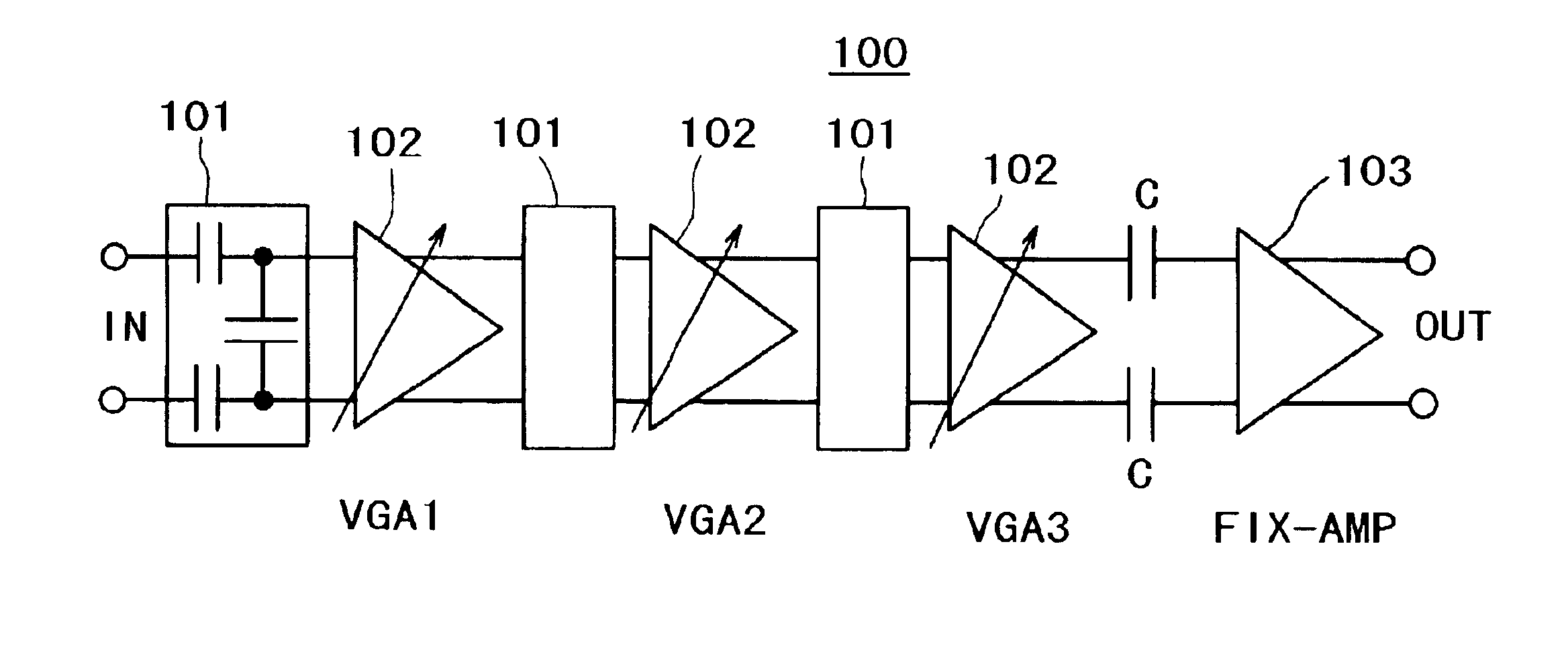
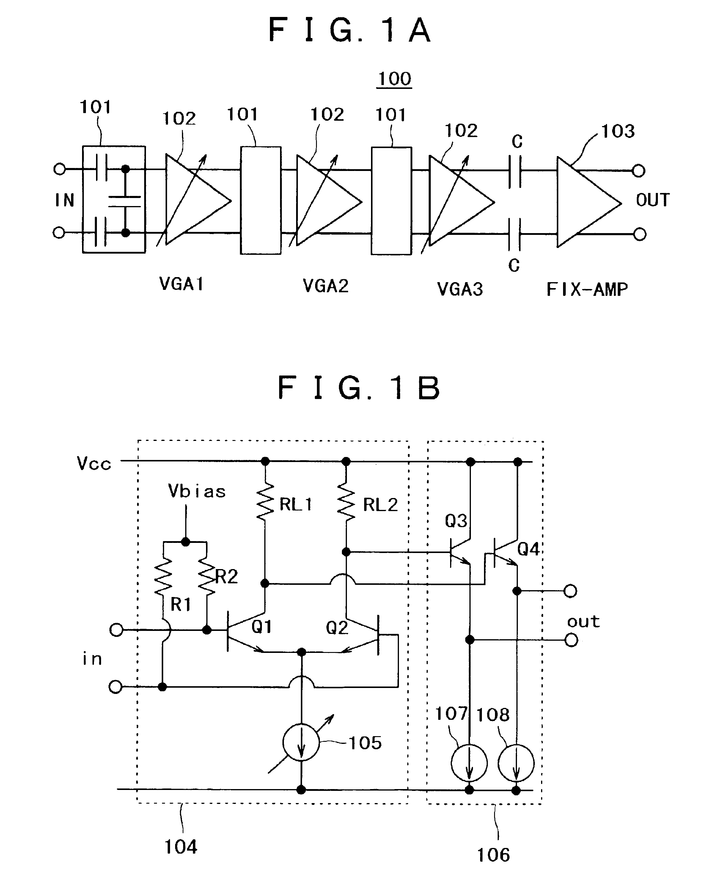
[0048]As with the first embodiment, the emitter follower 106 for driving a succeeding stage circuit is installed on the outlet side of the respective VGAs, and a fixed gain amplifier 103 is installed in the final stage of the variable gain amplifier in order to obtain a total gain as desired.

[0049]The variable gain differential amplifier 304 according to the present embodiment has a circuit configuration such that a single amplifier made of a transistor Q1 and another single amplifier made of a transistor Q2 are placed side by side for differentiation, and diodes D1, D2 are inserted in respective emitters of the transistor Q1, Q2, respectively. A gain of the variable gain differential amplifier 304 is controlled by control of current via the current mirror circuit 307 comprising a variable current source 308, resistor R3, transistor Q5, and diode D3.

[0050]The diodes D1, D2 inserted in the respective emitters of the variable gain differential amplifier 304 have effect of improving ci...

third embodiment

[0076]As with the case of the third embodiment, assuming a case by way of example where the linearity of the variable gain amplifier 406 is specified to be 0.1 dB-ICP, a specific design thereof is described hereinafter. It is theoretically known that the input distortion characteristic of the variable gain differential amplifier 304 shown in FIG. 3 for use in the respective unit amplifiers VGA1 to VGA3, making up the variable gain amplifier, does not undergo change in spite of a change in gain by changing bias current, and ICP is not dependent on the gain.

[0077]FIG. 9 shows simulation results indicating dependence of the gain AG of the variable gain differential amplifier 304 on an input signal level SIN. In FIG. 9, there is shown the characteristic of the variable gain differential amplifier 304 in the case where the gain is set to various values by changing control current (current Ic supplied from the variable current source 308 of the current mirror 307 to the collector of the t...


PUM


Abstract

A variable gain amplifier of low amplitude distortion, and low noise, having a large variable range, is provided. A variable gain differential amplifier that controls a gain by use of bias current is used as each of unit amplifiers (VGAs) making up the variable gain amplifier. A large variable gain range is obtained by series-connecting a plurality of the variable gain differential amplifiers. An attenuator is installed on the input side of the unit amplifier (VGA) at least in the initial stage. By doing so, it becomes possible to prevent amplitude distortion from occurring to the respective VGAs. An attenuator utilizing voltage division by capacitors, generating no noise, is used for lowering noise. Further, the variable gain amplifier is provided with a fixed gain amplifier installed in the final stage as necessary in order to obtain a total gain as desired. With the use of the variable gain amplifier as a variable gain amplifier for output power control of a polar loop transmitter, an excellent function for output power control can be achieved without causing significant deterioration in distortion characteristic and noise characteristic thereof.

Description

COPYRIGHT NOTICE[0001]A portion of the disclosure of this patent document contains material which is subject to copyright protection. The copyright owner has no objection to the facsimile reproduction by anyone of the patent document or the patent disclosure, as it appears in the Patent and Trademark Office patent file or records, but otherwise reserves all copyright rights whatsoever.BACKGROUND OF THE INVENTION[0002]1. Field of the Invention[0003]The invention generally relates to a variable gain amplifier and, more particularly, to a variable gain amplifier suitable for use in a semiconductor integrated circuit for communications.[0004]2. Discussion of Background[0005]A conventional variable gain amplifier may employ a variable gain amplifier, shown in FIG. 2A and FIG. 2B, as a configuration block. For more detail see non-patent document 1 below. The variable gain amplifier controls a gain with bias current by taking advantage of the gain of a transistor being proportional to the ...

Claims


Application Information

Patent Timeline
Patent Type & Authority Patents(United States)
IPC IPC(8): H03G1/00H03G3/30H04B1/04
CPCH03G1/0052H03G3/3042
Inventor KAJIWARA, HISAYOSHITOYOTA, KENJIHIKASA, KAZUHIKOYAMAWAKI, TAIZO
Owner RENESAS ELECTRONICS CORP
Why Eureka
Try Eureka