Antenna and radio device using the same

a radio device and antenna technology, applied in the field of antennas, can solve problems such as the price reduction of portable telephones, and achieve the effects of wide bandwidth, easy matching impedance, and high sensitivity

Inactive Publication Date: 2005-08-16
PANASONIC CORP
View PDF17 Cites 33 Cited by
  • Summary
  • Abstract
  • Description
  • Claims
  • Application Information

AI Technical Summary

Benefits of technology

[0008]The present invention addresses the problems discussed above, and aims to provide a built-in type antenna with a miniature size, wide bandwidth, high sensitivity, multi-band capability, and easy-to-match impedance and therefore a wireless device using the antenna with high productivity, low cost and good speech quality.

Problems solved by technology

Also, even though wide bandwidth and high sensitivity are pursued at the expense of miniaturization, a complicated impedance matching circuit will be required between the antenna and the radio frequency circuit thus presenting an obstacle for price reduction of portable telephones.

Method used


Image

  • Antenna and radio device using the same
  • Antenna and radio device using the same
  • Antenna and radio device using the same

Examples


exemplary embodiment 1

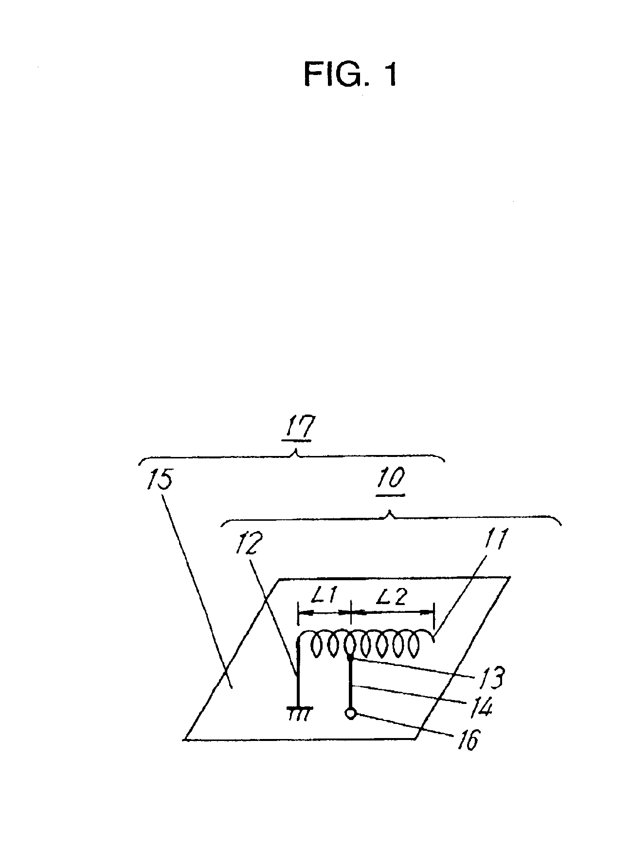
[0054]FIG. 1 illustrates an antenna configuration in Exemplary Embodiment 1 of the present invention. In FIG. 1, antenna element 11 is an element made by forming into a spiral (hereinafter referred to as spiral element or spiral element section) a ribbon or wire of a conductor made of a conductive metal such as copper, copper alloy, aluminum alloy, or stainless steel alloy, or one of these metals plated with a conductive metal such as Au or Ni. Antenna element 11 has an electric length corresponding to a desired frequency band. One end of spiral element 11 is left open and the other end is grounded to grounding conductor plate 15 through stub 12. Feeding point 13 in proximity to stub 12 is connected to feeder line 14. Grounding conductor plate 15 is disposed in a manner such that it is in parallel with the central axis of the spiral of antenna element 11 keeping a predetermined spacing. Spiral element 11 is secured on grounding conductor plate 15 by a support member (not shown in FI...

exemplary embodiment 2

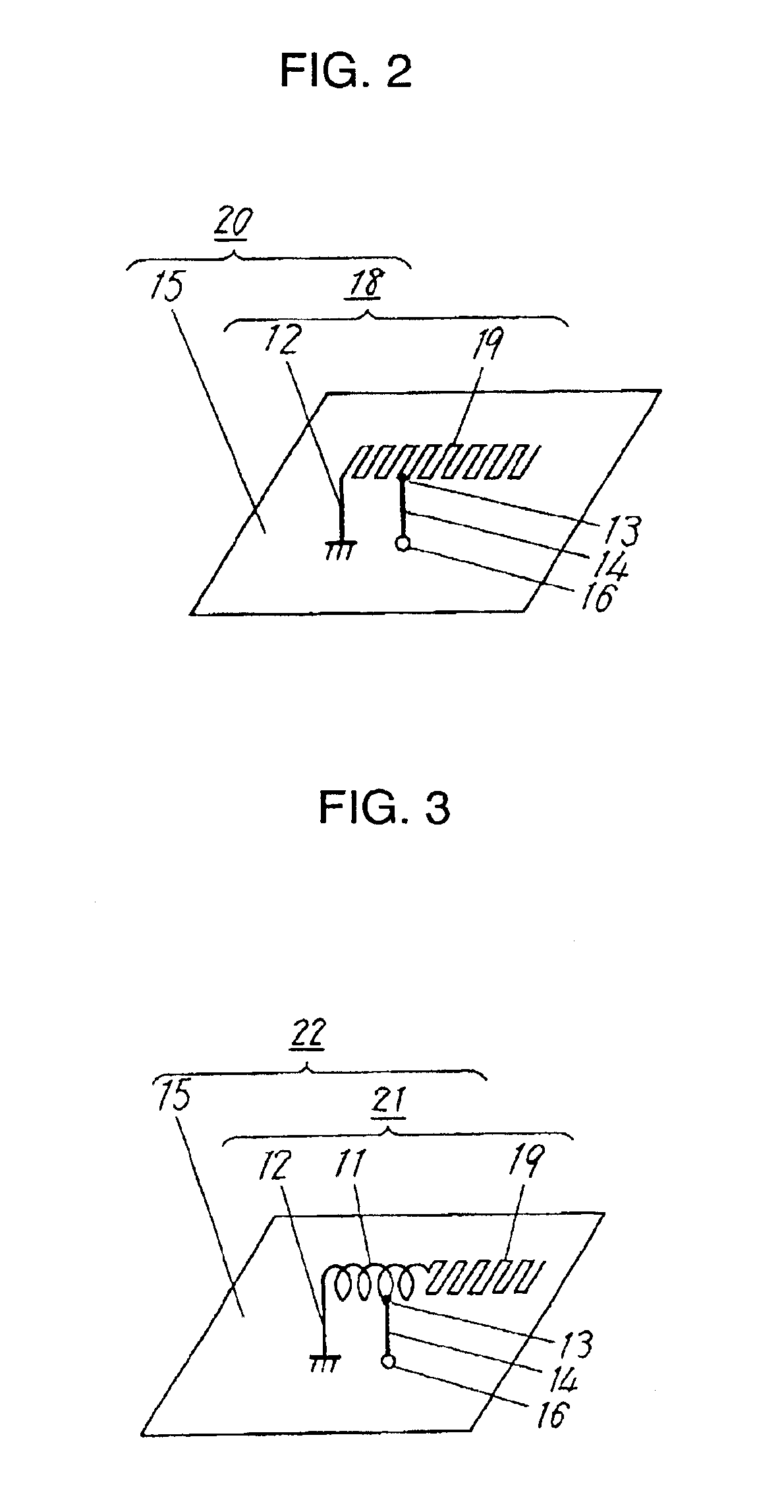
[0060]FIG. 2 illustrates an antenna configuration in Exemplary Embodiment 2 of the present invention. In FIG. 2, antenna 20 is configured in the same way as in above-described Exemplary Embodiment 1 with the exception that antenna element 19 of antenna main section 18 is composed of an antenna element that is meandrous in shape (hereinafter also referred to as meandrous element or meandrous element section).

[0061]By employing this configuration, it is possible to easily obtain a desired impedance characteristic in a desired frequency band by adjusting the distance between stub 12 and feeding point 13, the line width, length, pitch, etc., of meandrous element 19. Accordingly, it is possible to achieve a wider bandwidth and higher sensitivity as well as downsizing of the antenna. Furthermore, by the use of an antenna element that is meandrous in shape rather than a spiral antenna element used in Exemplary Embodiment 1, further thinning of antenna is also enabled.

exemplary embodiment 3

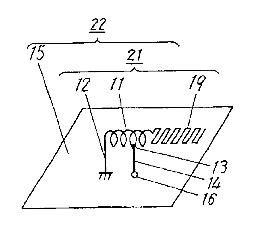
[0062]FIG. 3 illustrates an antenna configuration in Exemplary Embodiment 3 of the present invention. In FIG. 3, antenna 22 is configured in the same way as in above-described Exemplary Embodiment 1 and Exemplary Embodiment 2 with the exception that antenna main section 21 is composed of spiral element section 11 and meandrous element section 19.

[0063]By employing this configuration, it is possible to easily make a fine-tuning to obtain a desired impedance characteristic in a desired frequency band by adjusting the distance between stub 12 and feeding point 13, and the line width, length, pitch, etc., of spiral element section 11 and meandrous element section 19. Accordingly, it is possible to obtain wider bandwidth and higher sensitivity of the antenna with a higher accuracy. In this Exemplary Embodiment 3, a further flexible downsizing and low-profile design of an antenna are enabled by forming antenna element 21 with the combination of spiral element section 11 and meandrous elem...


PUM


Abstract

An inverted-F type antenna and a wireless device using the same. The antenna element comprises a grounding conductor plate and a conductor at least a part of which is generally spiral in shape and is disposed above the grounding conductor plate apart from the grounding conductor plate. A stub connects one end of the antenna element with the grounding conductor plate. A feeding point locates on the antenna element at a predetermined distance from one end of the antenna element and a feeder line electrically connects the feeding point with an external circuit. The antenna element is secured on the grounding conductor plate with a support member made of a dielectric material.

Description

TECHNICAL FIELD[0001]The present invention relates to antennas for installation in wireless devices such as for mobile communication and to wireless devices using the antennas.BACKGROUND ART[0002]In recent years, with the increasing demand for wireless devices for mobile communication, various communication systems have been developed, and a high performance, small, and light-weight wireless device that complies with a plurality of communication systems by an integrated unit is being desired to come out on the market. Accordingly, there is an inevitable demand for the development of antennas equipped in these wireless devices.[0003]Typical example of a device for such mobile communication is the portable telephone system, which is widely used all over the world and the frequency band of which varies depending on the area. As an example, the frequency band used for digital portable telephone system is 810 to 960 MHz in Japan for Personal Digital Cellular 800 (PDC800) system, and in E...

Claims


Application Information

Patent Timeline
Patent Type & Authority Patents(United States)
IPC IPC(8): H01Q9/42H01Q1/36H01Q9/04H01Q1/24H01Q3/24H01Q5/10H01Q9/30H01Q9/36H01Q21/30
CPCH01Q1/242H01Q1/243H01Q1/36H01Q9/0407H01Q9/42H01Q13/08
Inventor OHARA, MASAHIROTAKAGI, NAOYUKIINATSUGU, SUSUMU
Owner PANASONIC CORP
Why Eureka
Try Eureka