Transponder and antenna
a transponder and antenna technology, applied in loop antennas with ferromagnetic cores, instruments, reradiation, etc., can solve problems such as unsuitability and deterioration of characteristics, and achieve the effects of low loss, high frequency, and thin and flexibl
- Summary
- Abstract
- Description
- Claims
- Application Information
AI Technical Summary
Benefits of technology
Problems solved by technology
Method used
Image
Examples
experiment 1
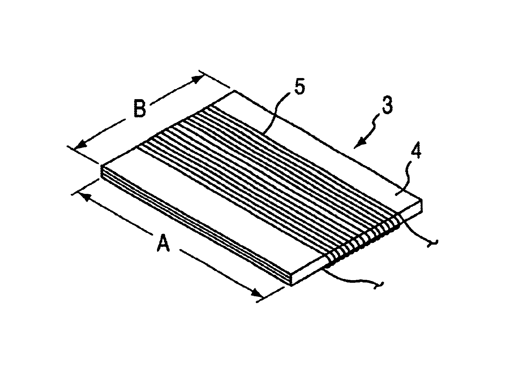
[0052]A sheet composed of Allied Signal METAGLAS 2714A having a width of 50 mm and a thickness 25 μm was used as a magnetic core material. The sheet was cut into a size shown in Table 1, was heated at 250° C. for 10 min. in air, and quenched. A magnetic core was produced by layering a few sheets so as to reach the thickness shown in Table 1. An insulation conductor having a diameter of 0.15 mm was wound up on the magnetic core so that the L of the coil is approximately 3 mH. The conductor was wound in the direction parallel to the longer side of the magnetic core in Examples, and in the direction parallel to the shorter side of the magnetic core in Comparative Examples.
[0053]The resistance of each antenna due to the magnetic core was evaluated by the following equation from the resistance R obtained from Yokogawa-Hewlett-Packard LCR meter 4284A:
R1=R−R2
wherein R1 represents a resistance due to the magnetic core, R represents an observed resistance, and R2 represents a direct current ...
experiment 2
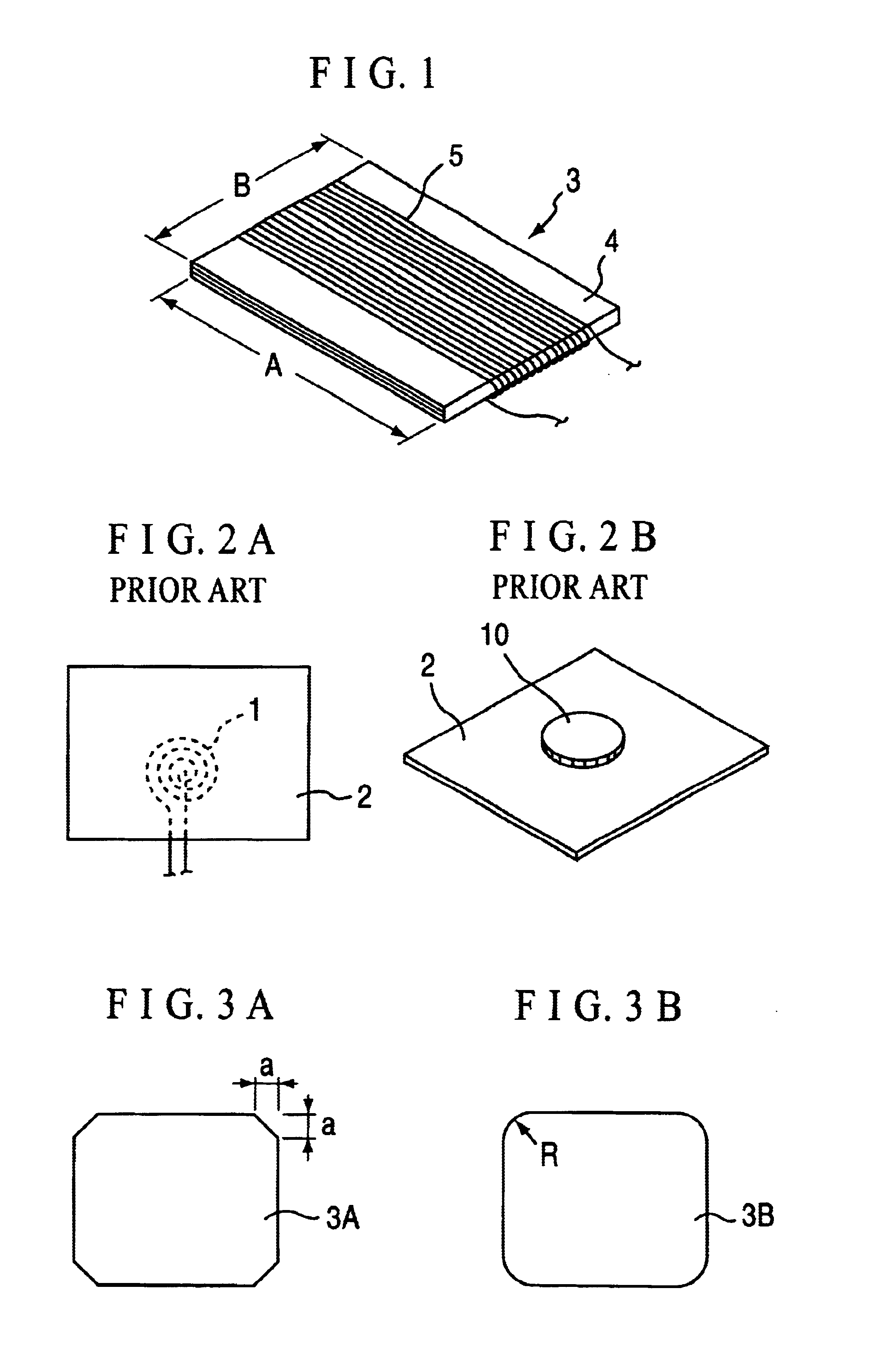
[0056]A sheet composed of Allied Signal METAGLAS 2714A having a width of 50 mm and a thickness 25 μm was cut into 50 mm by 25 mm. Four comers of the cut sheet in Example A were cut as shown in FIG. 3A (a=6 mm). Four comers of the cut sheet in Example B were rounded as shown in FIG. 3B so as to form arcs (R=6 mm). Each comer in Example C was maintained to right angle. Sheets were heated at 250° C. for 10 min. in air, and quenched. A magnetic core of each Example was produced by layering three sheets. An insulation conductor having a diameter of 0.15 mm was wound up twice by each 85 turns in the direction parallel to the longer side of the magnetic core to form an antenna. The direct current resistance of the coil was 20.4Ω.
[0057]The resistance of each antenna due to the magnetic core was evaluated similar to Experiment 1. Results are shown in Table 2. Table 2 demonstrates that the resistance significantly decreases by eliminating the comers of the magnetic core.
Experiments 3
example
[0058]A sheet composed of Allied Signal METAGLAS 2714A having a width of 50 mm and a thickness 0.025 mm was cut into 50 mm by 25 mm, heated at 250° C. for 10 min. in air, and quenched. A magnetic core was produced by layering three sheets. An insulation conductor having a diameter of 0.16 mm was wound up by 180 turns in the direction parallel to the longer side of the magnetic core.
COMPARITIVE EXAMPLE
[0059]On the other hand, an antenna composed of an air-core coil of which a conductor having a diameter of 0.016 mm was wound to 400 turns.
[0060](Measurement)
[0061]The resistance of the magnetic core of each sample, of which a 10-yen coin was placed in the coil center as shown in FIG. 2B, was measured similar to Experiments 1 and 2. Results are shown in Table 3. Table 3 demonstrates that the antenna of the Example exhibits a smaller resistance in a practical frequency region as a transponder of 40 to 200 kHz.
PUM
| Property | Measurement | Unit |
|---|---|---|
| thickness | aaaaa | aaaaa |
| diameter | aaaaa | aaaaa |
| thickness | aaaaa | aaaaa |
Abstract
Description
Claims
Application Information
 - R&D
- Intellectual Property
- Life Sciences
- Materials
- Tech Scout
- Unparalleled Data Quality
- Higher Quality Content
- 60% Fewer Hallucinations
Browse by: Latest US Patents, China's latest patents, Technical Efficacy Thesaurus, Application Domain, Technology Topic, Popular Technical Reports.
© 2025 PatSnap. All rights reserved.Legal|Privacy policy|Modern Slavery Act Transparency Statement|Sitemap|About US| Contact US: help@patsnap.com


