
Holographic printer

a printer and holographic technology, applied in the field of holographic printers, can solve the problems of unsuitable technology, high cost, and difficulty in writing such patterns once calculated, and achieve the effects of reducing noise results, increasing system flexibility, and high speed operation

Inactive Publication Date: 2005-08-16
COMPHARE TRUST COMPANY OF CANADA
View PDF33 Cites 39 Cited by
  • Summary
  • Abstract
  • Description
  • Claims
  • Application Information

AI Technical Summary

Benefits of technology

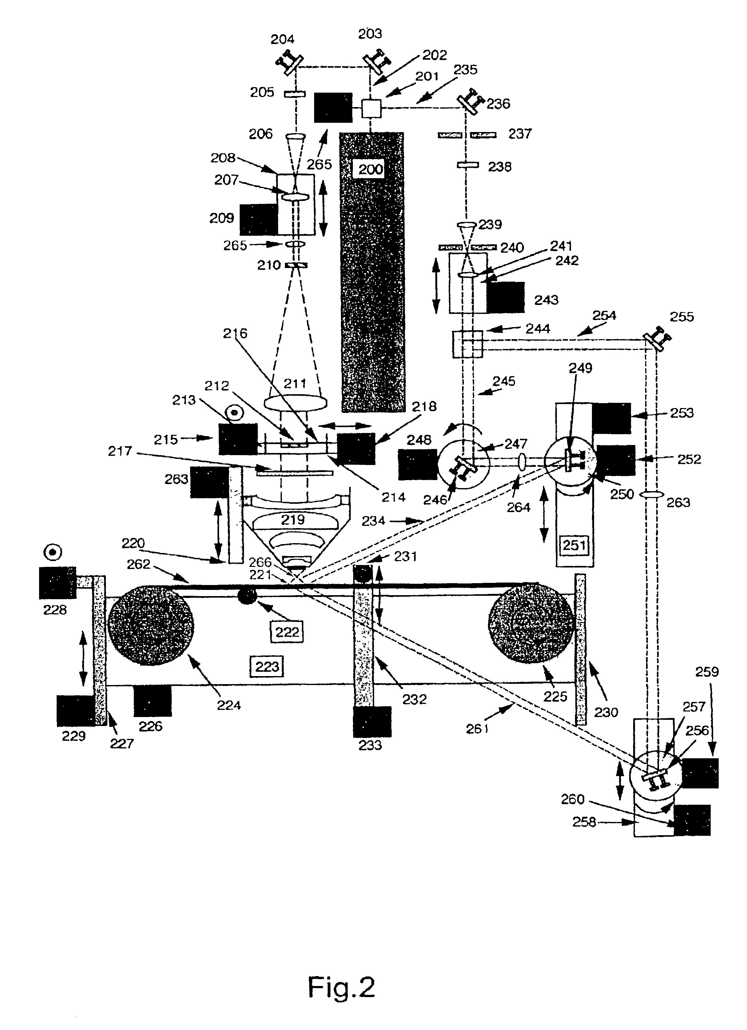
[0042]The step of using a pulsed laser as the laser source of a holographic printer is particularly advantageous since it enables the printer to operate without sensitivity to external or internal vibration or slight temperature fluctuations. In addition the speed of printing is fundamentally increased as there is no need to wait for vibration to dissipate before making an exposure. Thus the write speed is essentially determined by the refresh rate of the SLM used. Accordingly the preferred embodiment can work several orders of magnitude faster than conventional printers which use a CW laser and with a reliability of operation fundamentally higher.
[0214]Thus the preferred arrangement has many advantages over known arrangements including an energy requirement orders of magnitude lower than the prior art, dramatically increased system flexibility, lower noise results, higher speed operation and fundamentally smaller printer size.

Problems solved by technology

For many practical applications this technique is hence unsuitable.
However, even with today's computer resources, calculation of the interference pattern by Fourier transforms remains a daunting computational task for larger holograms.
In addition it is still highly difficult and costly to write such patterns once calculated, the preferred technique being by electron beam.
However, this latter system suffered from the disadvantage that the image should be located very close to the recording material.
Additionally, the system was unable to form holograms which faithfully reconstructed the directional properties of light emanating from each image point.
Foremost the use of a CW laser severely limits the write time of each holographic pixel.
In addition air currents, temperature changes and environmental sound will generally disturb the proper operation of such a printer.
Hence, the arrangement suffers from a low printing speed, and it is not practically possible to implement such a device outside of a strictly controlled laboratory environment.
Another disadvantage of the above system is that it can only produce holographic pixels of one size.
Such a system is not therefore able to continuously change the holographic pixel size and hence different formats of holograms which require fundamentally different pixel sizes can not be readily produced.
The use of contact apertures 1618, 1622 in the system, apart from being inflexible, is also highly problematic since the emulsion surface of the photosensitive material is very sensitive.
Another disadvantage of this arrangement is that it is only designed to produce monochromatic reflection type holograms.
The system is also unable to produce master H1 type holograms, and is similarly incapable of producing any form of multiple colour hologram.
Another disadvantage of the above system is that the wide-angle objective 1617 employed is designed to only minimize spherical aberration, is simplistic in design and only allows a restricted set of holographic formats to be produced.
Another disadvantage of the system is that the reference beam angle is fixed and cannot be controlled as may be required, for instance, to arrange for different hologram replay conditions.
This is particularly problematic at large format.
As is readily apparent, the above described holographic printer suffers from numerous problems which render it impractical to use commercially.
In addition, for large holograms, the time required to write a two dimensional array of holographic pixels is usually proportional to the square of the time required to write the H1 master hologram and as such can become prohibitively long for some applications.
Furthermore, a frequent complaint of directly written 1-step composite holograms is that the holograms appear “pixelated” whereas the 2-step technique of using an H1 master hologram is less prone to this problem.
Also in many applications quick previews of the final hologram are required and it is not generally convenient to produce an H1 hologram and then to put this hologram into another machine in order to generate the final H2 hologram.
Known 1-step and 2-step holographic printing processes employ CW lasers and thus, as a result, conventional holographic printing technology has been fundamentally slow and prone to vibrational disturbance.
There are many disadvantages of this system.
In addition air currents, temperature changes and environmental sound will generally disturb the proper operation of such a printer.
Hence the system suffers from a low printing speed and it is impractical to use such a device outside of a strictly controlled laboratory environment.
Another disadvantage of this holoprinter is that a diffusion screen is utilized onto which 2-D perspective view images are projected.
However a powerful laser is undesirable due to the problems of thermal heating of the various optical components, particularly the film 33, which must remain interferometrically static during each and every exposure.
Long exposure times are undesirable because of problems due to vibration.
Another disadvantage of the above system is that a diffusion screen, aside from being energetically inefficient, inevitably deteriorates the image quality.
Another disadvantage of the above system is that a point source is used to illuminate the film transparency and thus the final image fidelity will be severely limited.
Another disadvantage of the above system is that a large moving aperture must move in quasi-contact with the photosensitive emulsion surface.
This is usually very problematic as the emulsion of the photosensitive material 60 is usually highly fragile and yet if the aperture 58 is held at more than a very small distance from said emulsion surface then the quality of the generated hologram will rapidly fall.
A yet further disadvantage of the above arrangement is that the moving aperture will inevitably leave areas of the hologram which are either doubly exposed or unexposed, thus diminishing the quality.
Another disadvantage of the above arrangement is that it is only capable of making H1 type holograms and cannot directly write 1-step white-light-viewable holograms where the 3-D object bisects the hologram plane.
A further disadvantage of the above arrangement is that it is only capable of reasonably writing single parallax holograms as generalization of the technique to full parallax would render the technique hopelessly cumbersome given the above cited problems.

Method used


Image

  • Holographic printer
  • Holographic printer
  • Holographic printer

Examples


Embodiment Construction

5.1 Fundamental Image Data Required

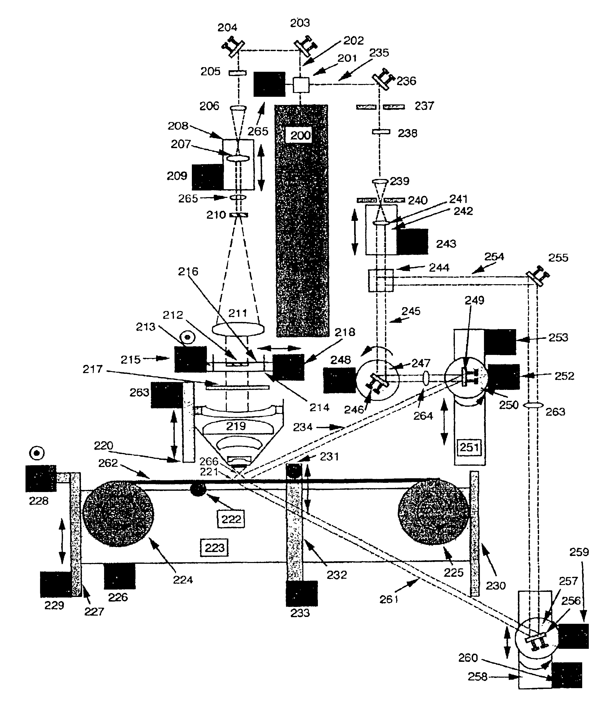
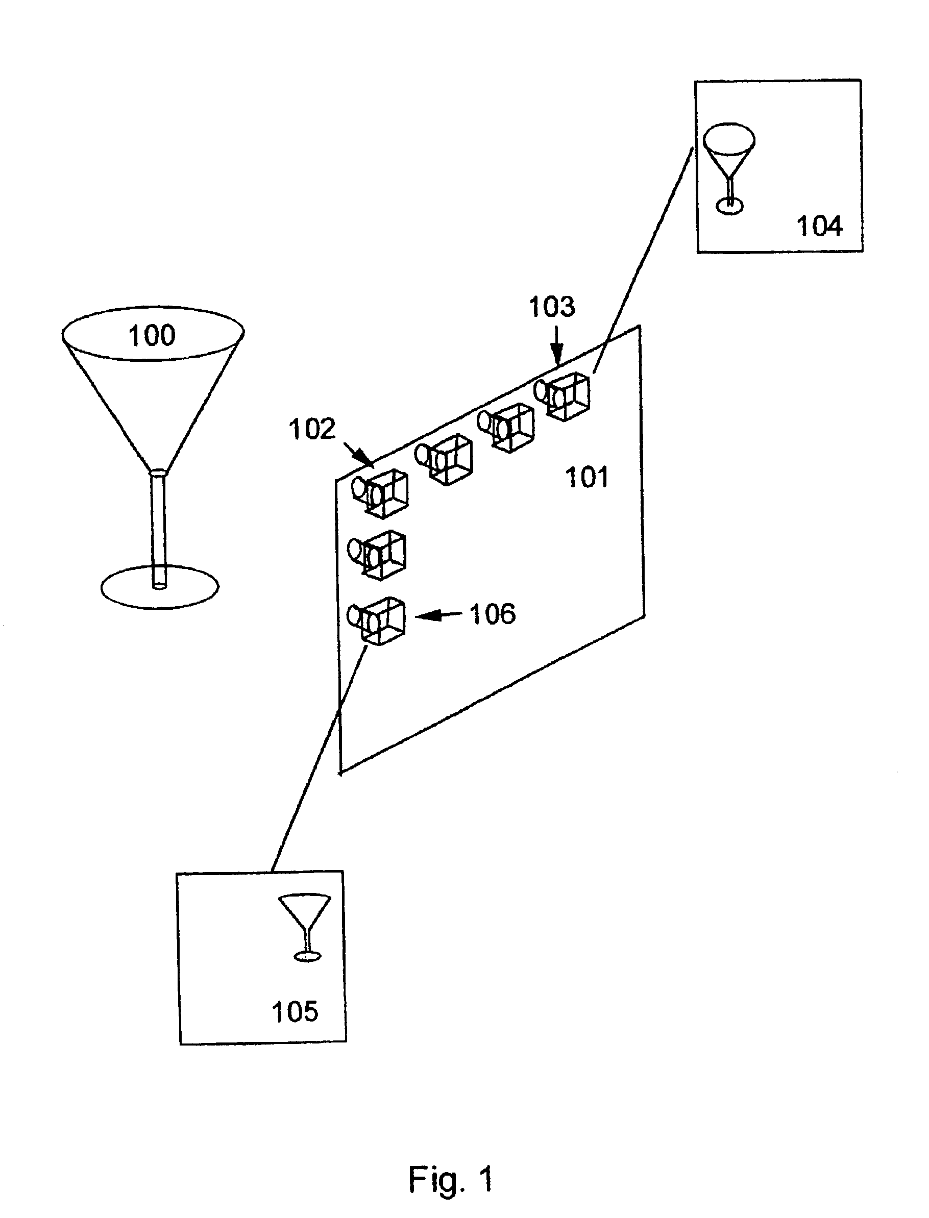
[0235]In one embodiment of this invention a computer is used to generate a three dimensional model of an object using a standard commercial computer program. Such computer programs can nowadays produce very lifelike models using a variety of sophisticated rendering processes that mimic real life effects. In addition advances in computer technology have now seen the calculation times, required for such programs to run, dramatically decreased. Three dimensional scanners using Moire or other principles now permit the incorporation of real world 3-D images in such computer models. The storage memory required for such 3-D models is largely dependent on the texture maps used therein and hence computer files representing such 3-D models are usually relatively small and may be transmitted over the internet easily. In the preferred embodiment of this invention said 3-D computer models are used to generate a series of 2-D camera views from a virtual viewing ...


PUM


Abstract

A single method and apparatus for producing many of the most common types of hologram from digital data is disclosed. The data are generated entirely by a computer as a 3-D (animated) model or from multiple 2-D camera images taken of a real 3-D (moving) object or scene from a plurality of different camera positions. The data are digitally processed and displayed on a small high resolution spatial light modulator (SLM). A compact low energy pulsed laser, is used to record composite holograms. The present invention permits the creation of restricted or full parallax master transmission or reflection type composite holograms, known as H1 holograms, that can be copied using traditional methods. Alternatively the same invention and apparatus permits the direct writing of hologram without the need to pass through the intermediate stage of the H1 transmission hologram.

Description

BACKGROUND OF THE INVENTION[0001]The present invention relates to holographic printers. According to a preferred embodiment a method and apparatus for recording and printing holographic stereograms from digital data is disclosed.[0002]For over 50 years holograms have been produced by the general technique of illuminating an object with coherent light and arranging that the scattered light falls onto a photosensitive recording material that is also illuminated by a mutually coherent reference beam (see for instance E. N. Leith et al., “Reconstructed Wavefronts and Communication Theory”, Journal of the Optical Society of America 53, 1377-81 1963). However, with such a technique one requires a physical object in order to make an holographic representation of this object and usually the size of the holographic image corresponds in a 1:1 fashion with the size of the object holographed. For many practical applications this technique is hence unsuitable.[0003]An alternative technique of ge...

Claims


Application Information

Patent Timeline
Patent Type & Authority Patents(United States)
IPC IPC(8): G03H1/26G03H1/24G03H1/00G02B13/00B41J2/44G02B13/22G03H1/12G03H1/16
CPCG03H1/24G03H1/268G03H1/0891G03H1/16G03H2001/0216G03H2001/0413G03H2001/0415G03H2001/0428G03H2001/0473G03H2001/2263G03H2001/2265G03H2001/2268G03H2001/2273G03H2001/2685G03H2001/269G03H2001/2695G03H2001/306G03H2210/22G03H2210/40G03H2210/42G03H2210/454G03H2222/22G03H2222/33G03H2222/50G03H2223/19G03H2210/441G03H2001/043
Inventor BROTHERTON-RATCLIFFE, DAVIDVERGNES, FLORIAN MICHAEL ROBERTRODIN, ALEXEYGRICHINE, MIKHAIL
Owner COMPHARE TRUST COMPANY OF CANADA
Learn More