Liquid metering system

a liquid metering and liquid technology, applied in the field of liquid metering system, can solve the problems of limited delivery accuracy of +/20%, inability to achieve the required accuracy of pharmaceutical delivery, and rare use of peristaltic pumps

Inactive Publication Date: 2005-08-23
THERAFUSE
View PDF31 Cites 68 Cited by
  • Summary
  • Abstract
  • Description
  • Claims
  • Application Information

AI Technical Summary

Problems solved by technology

Since the manufacturing tolerance on the inside diameter of economic elastomeric tubing is on the order of + / −10%, the delivery accuracy is limited to + / −20%.
Today, peristaltic pumps are seldom used for accurate delivery of pharmaceuticals.
However, the problem that these proposed schemes face is that they do not achieve the required accuracy of delivery of the pharmaceutical.
This problem is further compounded by the fact that the dependence on the inside diameter of the conduit is a fourth power dependence.
But the dimensions of the flow conduit, its cross section, and the temperature for viscosity control are left uncontrolled, with the result of inaccurate dispensing of the fluid.
However, in many liquid delivery systems, the conduit along which the liquid flows requires frequent replacement and, in the case of pharmaceutical infusion systems, the total flow path must also be kept sterile.
In this first class of types of flow meters, the added complexity of adding components, and their necessary leads and connectors to the replaceable conduits, causes the replacement conduits to be expensive.
And if these additional components are added to a reusable portion of the dispensing system, the replacement of the liquid container, or addition of fresh liquid to an existing container opens the flow path to an unsterile environment.
However, each of these patents fails to recognize that the measured time of flight and the calculated stream velocity are insufficient to completely correct for variations in system components.
And in situations where the conduit is to be replaced frequently, unless the inside diameter of the conduit is measured by the device or measured in the factory and communicated to the device, both expensive steps, the uncertainty due to the unknown inside diameter remains.
In the teachings of U.S. Pat. Nos. 4,777,368, 4,938,079, and 5,211,626 there are additional practical considerations that make these teachings difficult to reduce to practice in cost-effective commercial products.
Due to the high heat capacity and the rapid thermal diffusivity of virtually all liquids of commercial importance, and especially water, which is the base of all pharmaceutical infusion fluids, heating the liquid fast enough and to a high enough temperature to realize an operation flow meter is very difficult.
And the problem is especially acute for Frank since his teachings require the heat to pass through the wall of the conduit by conduction, which is especially time-consuming and lossy.
The second practical aspect which makes the prior art teaching, including the teaching in pending U.S. application Ser. No. 09 / 867,003, difficult to commercialize is the mode of detecting the heat pulse.
Detection methods relying on detecting the infrared radiation from such a small change in temperature, such as proposed by Frank in U.S. Pat. No. 5,211,626, Kerlin, Jr. in U.S. Pat. No. 4,938,079, and Sage, Jr. in pending U.S. application Ser. No. 09 / 867,003, must operate in the far infrared where detectors are either too slow to respond to the heated liquid or must be cooled, making them large, energy consuming and expensive.
Goldberg in U.S. Pat. No. 4,938,079 is sensitive to this issue, but offers no data to support a practical or operational device.

Method used


Image

  • Liquid metering system
  • Liquid metering system
  • Liquid metering system

Examples


Embodiment Construction

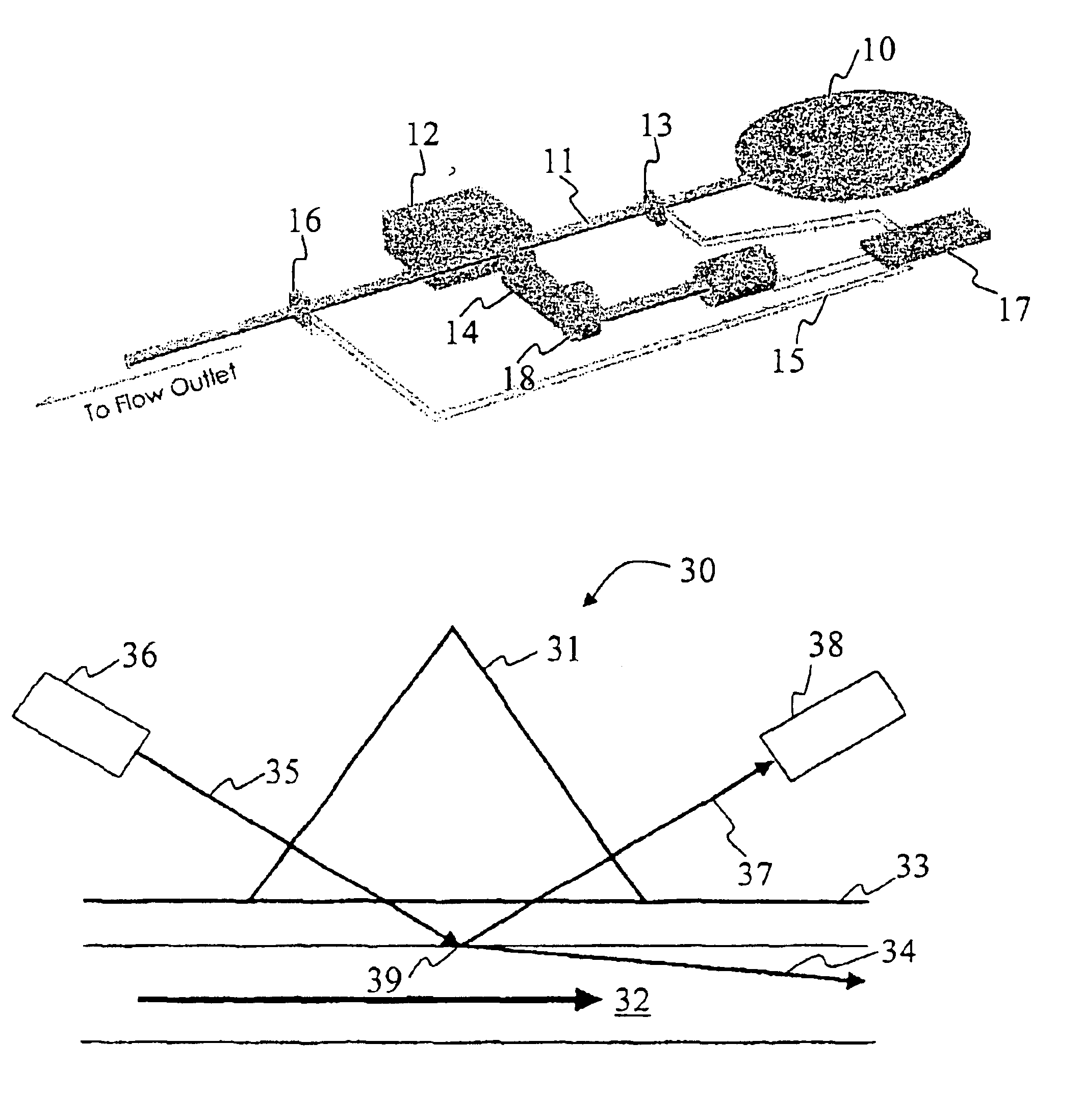
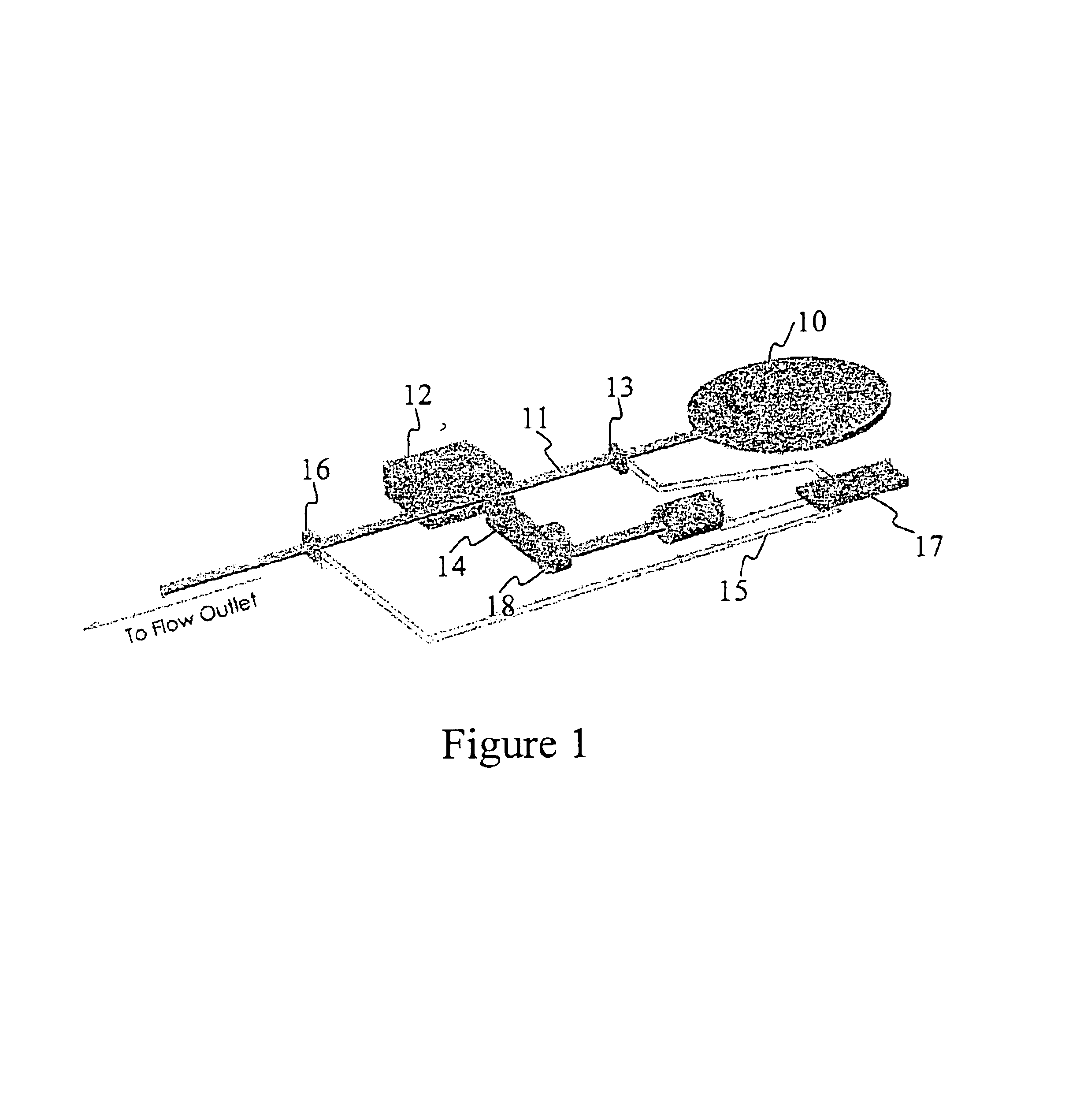
[0023]The optical flow meter of this invention will be described in terms of a liquid dispensing system for use in infusion of pharmaceutical solutions. FIG. 1 shows a block diagram of such a system. The liquid to be dispensed is contained in pressurized reservoir 10. When pinch tube member 14 is moved away from stop 12, conduit 11 is opened and the liquid is free to flow down conduit 11 to the flow outlet. When pinch tube 14 presses conduit 11 against stop 12, stopping flow, the liquid is not free to move down the conduit to the flow outlet. At a selected time, microprocessor 17 signals heating element 13 to heat the portion of the liquid at its location along the conduit. Once the portion of the liquid is heated, the pinch tube member is moved away from the conduit, and the liquid begins to flow. At some later time, the heated portion of the liquid passes heat sensor 16 where the heated portion is detected. The time required for the heated portion of the liquid to move from the lo...


PUM

PropertyMeasurementUnit
angle of incidenceaaaaaaaaaa
incident/reflected angleaaaaaaaaaa

Abstract

Systems and methods for measuring the flow of a liquid along a conduit are disclosed. A heat source applies thermal energy to a portion of a liquid flowing along a conduit thereby elevating its temperature. An optical sensing means comprising a light source illuminating the liquid in the conduit downstream from the position of application of the thermal energy and an optical detector receiving a portion of this illumination senses the heated portion of liquid by measures a change in an optical property of the illumination caused by a change in the index of refraction of the heated portion of liquid. The time required for the heated portion of the liquid to move from the point of application of thermal energy to the point of optical sensing is measured. This measured time, along with the distance of separation of the heat source and the optical sensing means permits calculation of the velocity of the liquid in the conduit.

Description

[0001]This application claims subject matter disclosed in copending application Ser. No. 09 / 867,003 filed May 29, 2001.BACKGROUND OF THE INVENTION[0002]A. Field of the Invention[0003]This invention relates to the measurement of properties of liquids moving in a conduit and specifically the measurement of the flow rate of a liquid moving at a relatively low flow rate of less than one liter per minute in a conduit. Most specifically, it relates to the measurement of the rate of infusion of therapeutic agents to patients to achieve highly accurate dosing of these patients according to a prescribed administration regimen.[0004]B. Related Art[0005]Many methods of measuring the flow rate of liquids, and in particular the rate of infusion of a pharmaceutical to a patient are known. Best known are positive displacement systems wherein a known volume of fluid is moved over time independent of other system parameters such as pressure and liquid viscosity. Today, the most commonly used positiv...

Claims


Application Information

Patent Timeline
Patent Type & Authority Patents(United States)
IPC IPC(8): G01F1/704G01F1/708
CPCG01F1/7044G01F1/7084G01F1/7086A61M5/1452A61M5/16886A61M2005/16863A61M2205/3306A61M2205/3368
Inventor SAGE, BURTON H.CATANZARO, BRIAN E.
Owner THERAFUSE
Why Eureka
Try Eureka