Planar fluorescent lamp having particular electrode structure

Inactive Publication Date: 2005-08-23
DELTA ELECTRONICS INC
View PDF6 Cites 6 Cited by
  • Summary
  • Abstract
  • Description
  • Claims
  • Application Information

AI Technical Summary

Benefits of technology

[0014]This invention provides a planar fluorescent lamp. As rod electrodes are parallel to each other and adjacent to a glass rim, the luminescent area of the planar fluorescent lamp is increased.
[0015]The invention provides a planar fluorescent lamp, which can prevent the joint between the electrode and the electrode lead thereof from peeling during thermal process. The yield of the planar fluorescent lamp is enhanced, and the fabrication cost is reduced.
[0018]In the present invention, the planar fluorescent lamp is so designed to avoid the electrode leads occupying a certain area, so as to increase the luminescent area. The peeling effect of the joint between the electrode leads and the electrodes during a thermal process is also prevented.
[0021]In the electrode design of the planar fluorescent provided by the present invention, being preformed with a serrate structure, the electrodes are soldered with electrode leads. This structure allows the electrodes to release thermal stress during thermal process. The yield can thus be enhanced.

Problems solved by technology

However, the white fluorescent lamp is a non-planar line light source.
However, the brightness of the edge-light type is smaller due to a poorer application efficiency of light.
The fabrication cost is thus increased.
The electrodes assembly of the planar fluorescent is directional, and is inconvenient for automatic production.
The fabrication of electrode is complex.
Being restricted with the planar electrodes, the thinning process of the planar fluorescent lamp is affected.
While assembling the planar electrodes, fluorescent layer on the panel is easily scratched by the protruding edge.

Method used


Image

  • Planar fluorescent lamp having particular electrode structure
  • Planar fluorescent lamp having particular electrode structure
  • Planar fluorescent lamp having particular electrode structure

Examples


first embodiment

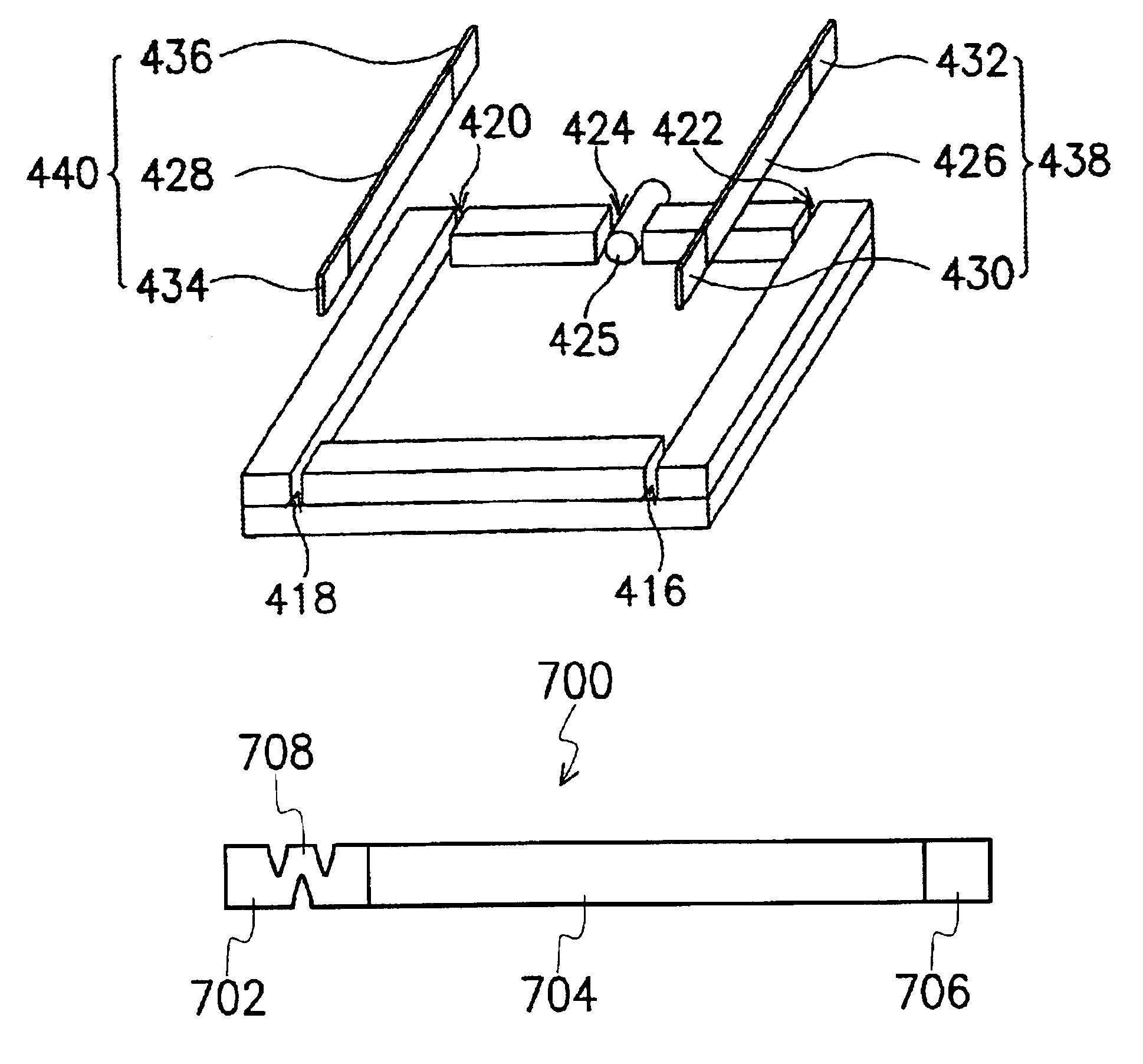
[0048]Referring to FIGS. 4A to 4D, top and 3-D views of a planar fluorescent and the method fabricating the same in a first embodiment of the invention are shown.

[0049]In FIG. 4A, a glass panel 400 is provided. A fluorescent layer 404 is coated on a surface 402 of the glass panel 400. The method for forming the fluorescent layer 404 includes screen printing, wet dip and electrostatic coating. The material of the fluorescent layer 404 includes phosphor, for example, tri-wavelength phosphor which can absorb ultra-violet light to emit blue, red and green lights. The thickness H of the glass panel 400 is about 2 mm to about 5 mm, preferably 3 mm. The material of the glass panel 400 includes soda-lime glass such as Corning®0800 glass or Corning®7059 glass.

[0050]Referring to FIG. 4B, a glass frit is used to fix the glass rims 406, 408, 410, 412 and 414 on an edge of the surface of the glass panel 400. Gaps are reserved between glass rims 406 and 408, glass rims 408 and 410, glass rims 410...

second embodiment

[0055]The fabrication method for the planar fluorescent lamp provided in the second embodiment is the same as that in the first embodiment. The difference is the fabrication method of the electrodes 438, 440. Referring to FIG. 5, the electrodes 538, 540 are formed by directly soldering the electrodes panels 500, 502 with the electrode leads 530, 532 and 534, 536.

third embodiment

[0056]The fabrication method for the planar fluorescent lamp provided in the third embodiment is the same as that in the first embodiment. The difference is the fabrication method of the electrodes 638, 640. Referring to FIG. 6A, a cross sectional view of an electrode is shown. An electrode lead 600 is provided. The length of the electrode lead 600 is about the sum of the lengths of the electrode 500 and the electrode leads 530, 532. At a proper position, a material layer 602 made of the electrode material is formed to wrap the electrode lead 600, so as to form an electrode 640. Similarly, the electrodes 638, 640 are formed. The method for fanning the material layer 602 includes electroplating, for example.

[0057]Referring to FIG. 6B, similar to the previous embodiment, the electrodes 638, 640 are disposed in the electrode seats 622, 624, 620 and 626 between the glass rims 610 and 612, 612 and 614, 614 and 616, 618 and 610. The length of the material layer 602 is the distance between...


PUM


Abstract

A planar fluorescent lamp having a first panel, a second panel, a glass rim, a venting tube, and a set of electrodes. Fluorescent layers are formed on both the first panel and the second panel. The glass rim is mounted on edges of the first and second panels. A recess and a gap are formed in the glass rim; the recess is used for placing the electrodes while the gap is reserved for installing the venting tube. The first panel, the second panel, and the glass rim are so arranged so that a cavity is formed thereby. The cavity is vacuumed via the venting tube and mercury vapor and inert gas are then introduced into the cavity.

Description

CROSS-REFERENCE TO RELATED APPLICATION[0001]This application claims the priority benefit of Taiwan applications serial nos. 89121895 and 89121895A01, filed Oct. 19, 2000 and Sep. 4, 2001.BACKGROUND OF THE INVENTION[0002]1. Field of the Invention[0003]This invention relates in general to a fluorescent lamp, and more particularly, to a planar fluorescent lamp that can be used as the backlight for a large area liquid crystal display (LCD).[0004]2. Description of the Related Art[0005]Having the advantages of high image quality, small volume, low driving voltage, low power consumption and a wide range of application, the liquid crystal display has been broadly applied to consuming products to replace the conventional cathode ray tube (CRT). The application of the liquid crystal display includes medium-and small-size portable television, cellular phone, camcorder, notebook computer, desktop computer, projection-type television and other computer products. However, different from the self-...

Claims


Application Information

Patent Timeline
IPC IPC(8): H01J61/30G02F1/1335G02F1/13H01J61/067G02F1/13357H01J61/36
CPCH01J61/305G02F1/133604
Inventor JEAN, RUEY-FENGCHEN, CHIH-FANGTSAI, KUANG-LUNGCHEN, LAI-CHENGLIN, SHIH-HSIENCHIANG, SHIEN-TSUNGCHEN, CHUN-CHIENCHANG, CHENG-YI
Owner DELTA ELECTRONICS INC
Why Eureka
Try Eureka