Time domain radio transmission system

a radio transmission system and time domain technology, applied in the field of radio systems, can solve the problems of prolonging the length of a signal burst, adversely affecting the coupling of signals to antennas, interfering with the signal radiated, etc., and achieves the effects of increasing the security of the system, wide frequency dispersion, and fast repetition ra

Inactive Publication Date: 2005-08-23
TIME DOMAIN
View PDF86 Cites 108 Cited by
  • Summary
  • Abstract
  • Description
  • Claims
  • Application Information

AI Technical Summary

Benefits of technology

[0012]Further, transmitted burst signals may be varied in time pattern (in addition to a modulation pattern for communications or telemetry). This greatly increases the security of the system and differentiates signals from nearly, if not all, ambient signals, that is, ambient signals which are not synchronous with transmitted burst signals. This also enables the employment of faster repetition rates with radar which would, absent such varying or dithering, create range ambiguities as between returns from successive transmission and therefore ranges. Bu...

Problems solved by technology

As a further consideration, power restraints in the past have been generally limited to the application of a few hundred volts of applied signal energy to the transmitting antenna.
In this manner, no metallic triggering communications line extends to ...

Method used


Image

  • Time domain radio transmission system
  • Time domain radio transmission system
  • Time domain radio transmission system

Examples


Embodiment Construction

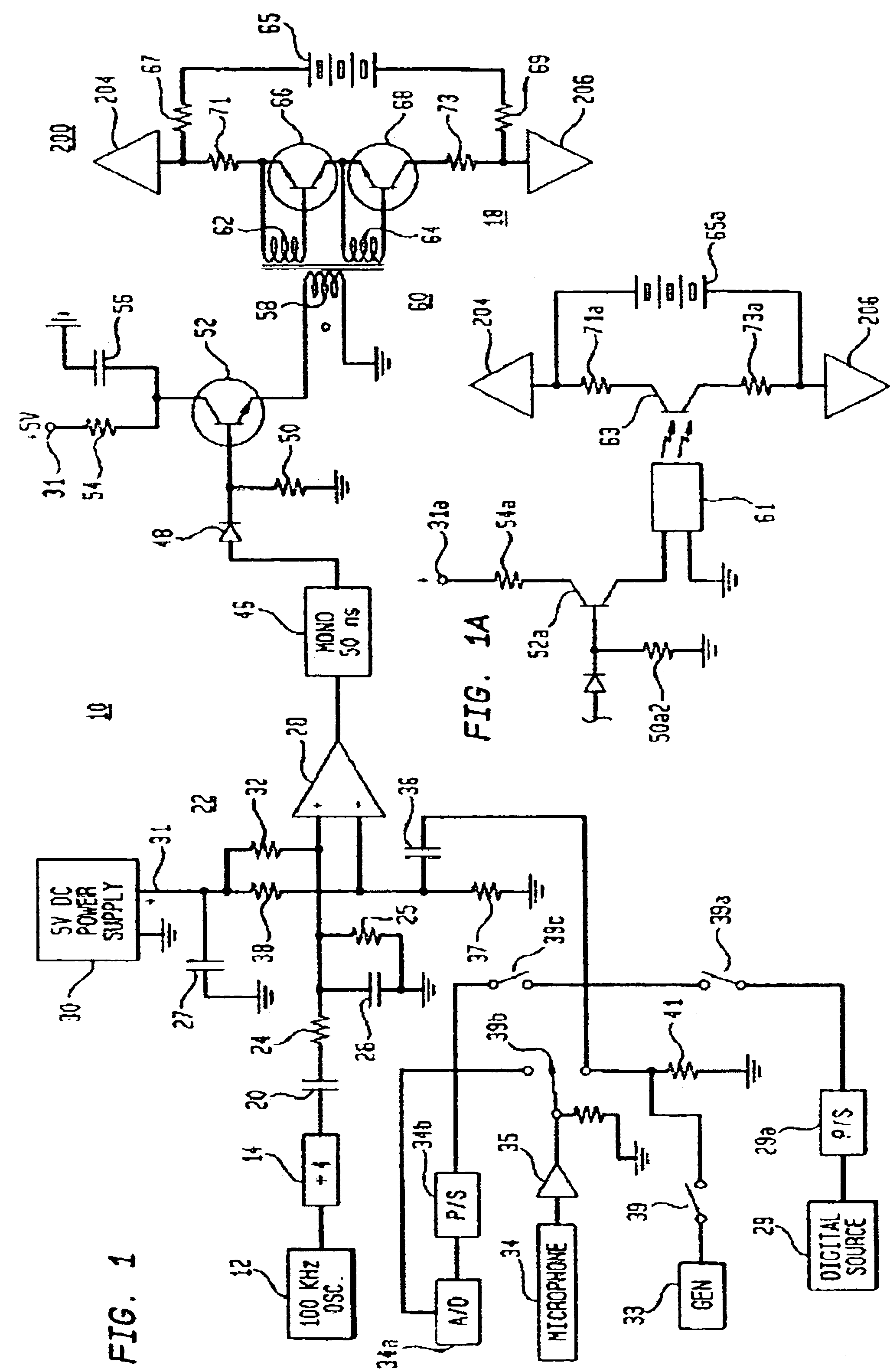
[0036]Referring to FIG. 1, and initially to transmitter 10, a base frequency of 100 kHz is generated by oscillator 12, typically being a crystal controlled oscillator. Its output, a pulse signal, is applied to ÷4 divider 14 to provide at its output a 25-kHz (0 to 5 volts) pulse signal shown in waveform A of FIG. 3. Further alphabetic references to waveforms will simply identify them by their letter identity and will not further refer to the figure, which will be FIG. 3. The 25-Khz output is employed as a general transmission signal.

[0037]The output of ÷4 divider 14 is employed as a signal base and as such is supplied through capacitor 20 to pulse position modulator 22. Pulse position modulator 22 includes in its input an RC circuit consisting of resistor 24 and capacitor 26 which convert the square wave input to an approximately triangular wave as shown in waveform B, it being applied across resistor 25 to the non-inverting input of comparator 28. A selected or reference positive vo...


PUM


Abstract

A time domain communications system wherein a broadband of time-spaced signals, essentially monocycle-like signals, are derived from applying stepped-in-amplitude signals to a broadband antenna, in this case, a reverse bicone antenna. When received, the thus transmitted signals are multiplied by a D.C. replica of each transmitted signal, and thereafter, they are, successively, short time and long time integrated to achieve detection.

Description

CROSS-REFERENCE TO RELATED APPLICATIONS[0001]This patent application is a continuation of U.S. application Ser. No. 10 / 186,306, filed Jun. 28, 2002, now abandoned, which is a continuation of U.S. application Ser. No. 09 / 419,806, filed Oct. 18, 1999, now U.S. Pat. No. 6,606,051, which is a continuation of U.S. application Ser. No. 08 / 978,367, filed Nov. 25, 1997, now U.S. Pat. No. 5,969,663, which is a continuation-in-part of U.S. application Ser. No. 08 / 335,676, filed Nov. 8, 1994, now abandoned, which is a continuation-in-part of U.S. application Ser. No. 07 / 846,597, filed Mar. 5, 1992, now U.S. Pat. No. 5,363,108, which is a continuation of U.S. application Ser. No. 07 / 368,831, filed Jun. 20, 1989, now abandoned, which is a continuation-in-part of U.S. application Ser. No. 07 / 192,475, filed May 10, 1988, now abandoned, which is a continuation-in-part of U.S. application Ser. No. 06 / 870,177, filed Jun. 3, 1986, now U.S. Pat. No. 4,743,906.[0002]The above-named prior patent applicat...

Claims


Application Information

Patent Timeline
IPC IPC(8): G01S13/00G01S13/18G01S13/02G01S7/28G01S7/282G01S7/292H01Q9/04H01Q9/28H01Q9/40H01Q21/06H04B1/69H04B1/7163H04B1/717H04B1/7183H04B14/02
CPCG01S7/282G01S7/292G01S13/0209G01S13/18H01Q9/28H01Q9/40H01Q21/061H04B1/69H04B1/71637H04B1/7174H04B1/7183H04B14/026H04L27/103
Inventor FULLERTON, LARRY W.
Owner TIME DOMAIN
Why Eureka
Try Eureka