Three terminal magnetic head having a magnetic semiconductor and a tunnel magnetoresistive film and magnetic recording apparatus including the head

a three-terminal magnetic head and semiconductor technology, applied in the field of three-terminal magnetic heads, can solve the problems of extremely small order of 1 na

Inactive Publication Date: 2005-08-23
HITACHI LTD
View PDF5 Cites 19 Cited by
  • Summary
  • Abstract
  • Description
  • Claims
  • Application Information

AI Technical Summary

Benefits of technology

[0005]The present invention pertains to a magnetic head for an ultrahigh-density recording/reproducing apparatus and it is therefore an object of the present invention to provide a device which fulfills the following tasks presented by a conventional three terminal magnetoresista...

Problems solved by technology

Although the injection of hot electrons is effective in increasing the output of the MR device, a problem is encountered that a col...

Method used


Image

  • Three terminal magnetic head having a magnetic semiconductor and a tunnel magnetoresistive film and magnetic recording apparatus including the head
  • Three terminal magnetic head having a magnetic semiconductor and a tunnel magnetoresistive film and magnetic recording apparatus including the head
  • Three terminal magnetic head having a magnetic semiconductor and a tunnel magnetoresistive film and magnetic recording apparatus including the head

Examples


embodiment 1

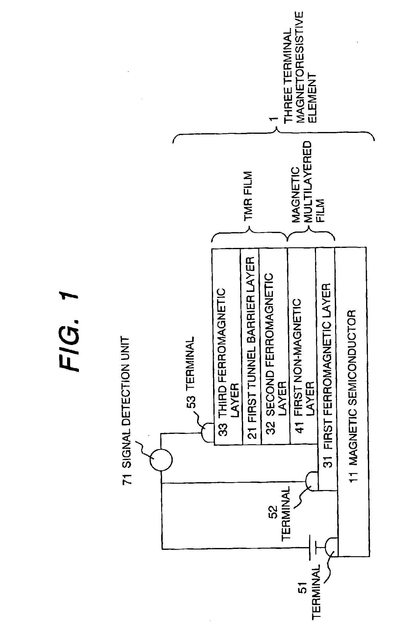
[0029]FIG. 1 shows one of the embodiments of the present invention. A first ferromagnetic layer 31 is formed on a magnetic semiconductor 11 and a first non-magnetic layer 41 is formed thereon to form a magnetic multilayer film. A second ferromagnetic layer 32, a first tunnel barrier layer 21, and a third ferromagnetic layer 33 are stacked successively on the magnetic multilayer film, thereby forming a tunnel magnetoresistive film.

[0030]Electrodes 51, 52, and 53 are disposed on respective end portions of the magnetic semiconductor 11, the first ferromagnetic layer 31, and the third ferromagnetic layer 33. The electrode 52 may also be disposed on any of the first ferromagnetic layer 31, the first non-magnetic layer 41, and the second ferromagnetic layer 32. The electrodes 51, 52, and 53 are insulated from each other such that an electric leakage does not occur.

[0031]A description will be given next to the principle of operation of the three terminal magnetoresistance device according ...

embodiment 2

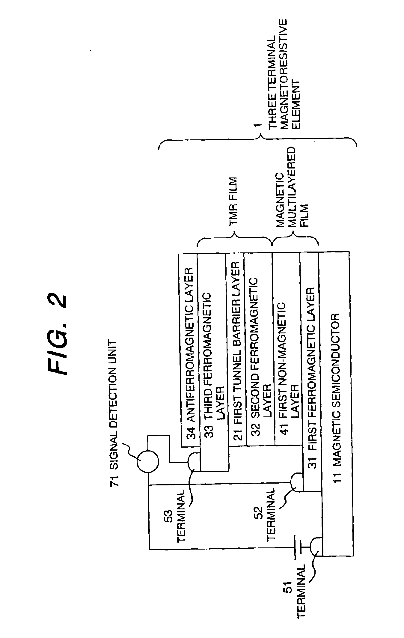
[0037]FIG. 2 shows a structure obtained by providing an antiferromagnetic layer on the third ferromagnetic layer in the structure shown in FIG. 1. The device formation method was implemented by using photolithograph), etching, and EB lithography in the same manner as in EMBODIMENT 1. The antiferromagnetic layer 34 was made of MnPt12 nm. The electrode 53 may also be disposed on the third antiferromagnetic layer 34, as shown in FIG. 3. The magnetoresistance effect obtained in the three terminal magnetoresistance device thus produced was 300%. The current between the electrodes 52 and 53 was 100 μA. In the structure, the antiferromagnetic layer performs the function of fixing the direction of magnetization of the third ferromagnetic layer and increasing the output.

embodiment 3

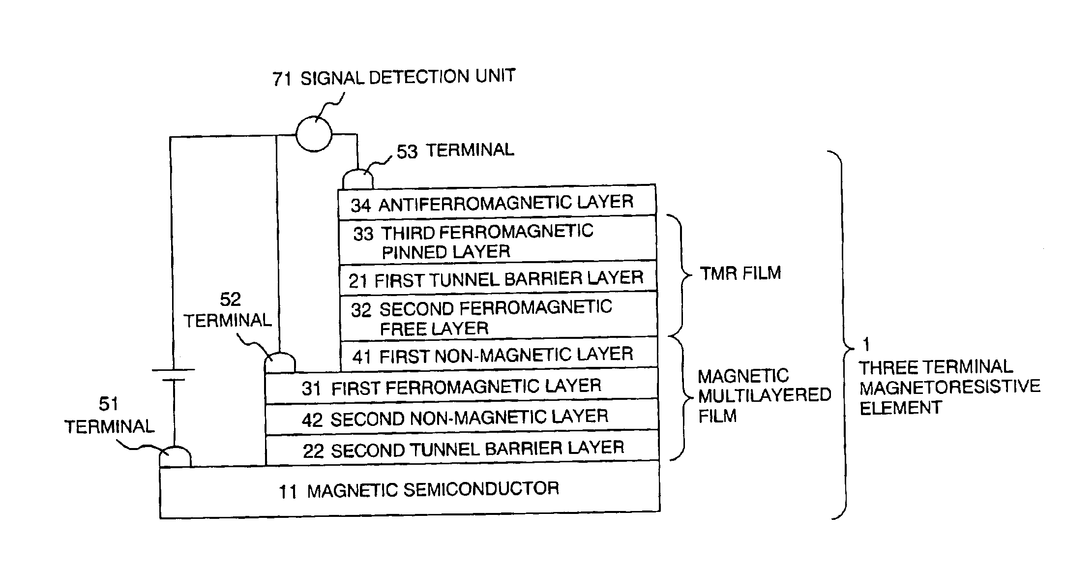
[0038]FIG. 4 shows a structure obtained by providing a second tunnel barrier layer 22 between the first ferromagnetic layer 31 and the magnetic semiconductor 11 in the structure shown in FIG. 3.

[0039]The device formation method was implemented by using photolithography, etching, and EB lithography in the same manner as in EMBODIMENT 1.

[0040]The provision of the second tunnel barrier 22 allows control of the state of electrons formed at the interface with the magnetic semiconductor 1. Since a tunnel current allows a current to flow ballistically from the magnetic semiconductor in the present embodiment, the efficiency with which highly polarized spins are injected is increased so that the output is increased. The magnetoresistance effect obtained in the present embodiment was 400 and the current obtained was 100 μA.


PUM


Abstract

A three terminal magnetoresistance head capable of providing a high output and a large output current is provided. A MIS junction multilayer film composed of a magnetic semiconductor, a metal magnetic multilayer film, and a tunnel magnetoresistance element is applied to a three terminal magnetoresistance device.

Description

BACKGROUND OF THE INVENTION[0001]1. Field of the Invention[0002]The present invention relates to a three terminal magnetic head using a three terminal magnetoresistance device in a head for magnetically reproducing information recorded magnetically and to an ultrahigh-density magnetic recording / reproducing apparatus comprising the three terminal magnetic head.[0003]2. Description of the Related Art[0004]For use in a reproducing portion of a magnetic head used in a high-density magnetic recording apparatus, a CIP-GMR (Current-In-Plane Giant Magnetoresistance) device which allows a current to flow in the in-plane direction of a film and a tunnel magnetoresistance device have been proposed, which are disclosed in Japanese Unexamined Patent Publication No. HEI 4-358310 (Patent Document 1) and Japanese Unexamined Patent Publication No. HEI 10-4227 (Patent Document 2), respectively. On the other hand, “Physical Review Letters. Vol. 85, 3277 (2000) (Non-Patent Document 1) has recently repo...

Claims


Application Information

Patent Timeline
IPC IPC(8): G11B5/39H01F10/16H01F10/32H01L43/08H01L43/10
CPCB82Y10/00B82Y25/00G11B5/3906G11B5/3909
Inventor HAYAKAWA, JUNITO, KENCHI
Owner HITACHI LTD
Why Eureka
Try Eureka