Apparatus and method for measurement of the magnetic induction tensor using triaxial induction arrays

Active Publication Date: 2005-08-23
EXXONMOBIL UPSTREAM RES CO
View PDF16 Cites 33 Cited by
  • Summary
  • Abstract
  • Description
  • Claims
  • Application Information

AI Technical Summary

Problems solved by technology

These techniques are often unsuccessful because of the inappropriateness of these instruments and techniques for use in any environment except vertical wells or isotropic media.
Despite commercial quantities of high resistivity hydrocarbon-bearing sandstones surrounding the instru-, ment in the reservoir, the apparent resistivity does not unambiguously reflect the presence of these hydrocarbons.
Conversely, compared to the vertical wells, the apparent resistivity responses of horizontal wells are too high in the presence of anisotropy.
However, in the general case of a fully anisotropic medium and a deviated well, conventional instruments cannot be used to uniquely infer or accurately estimate any of the six components of the conductivity tensor.
The primary component of the field is much larger than the secondary field making detection of the secondary field in the presence of the primary field problematic.
Conventional induction instrumentation cannot quantify the conductivity distribution in such media because the axial dipole transmitters and receivers are not capable of sampling the full magnetic induction data space.
Therefore, fluid volume interpretations based upon this conductivity estimate are often misestimated.
A possible reason for the lack of collocated transmitters

Method used


Image

  • Apparatus and method for measurement of the magnetic induction tensor using triaxial induction arrays
  • Apparatus and method for measurement of the magnetic induction tensor using triaxial induction arrays
  • Apparatus and method for measurement of the magnetic induction tensor using triaxial induction arrays

Examples


example

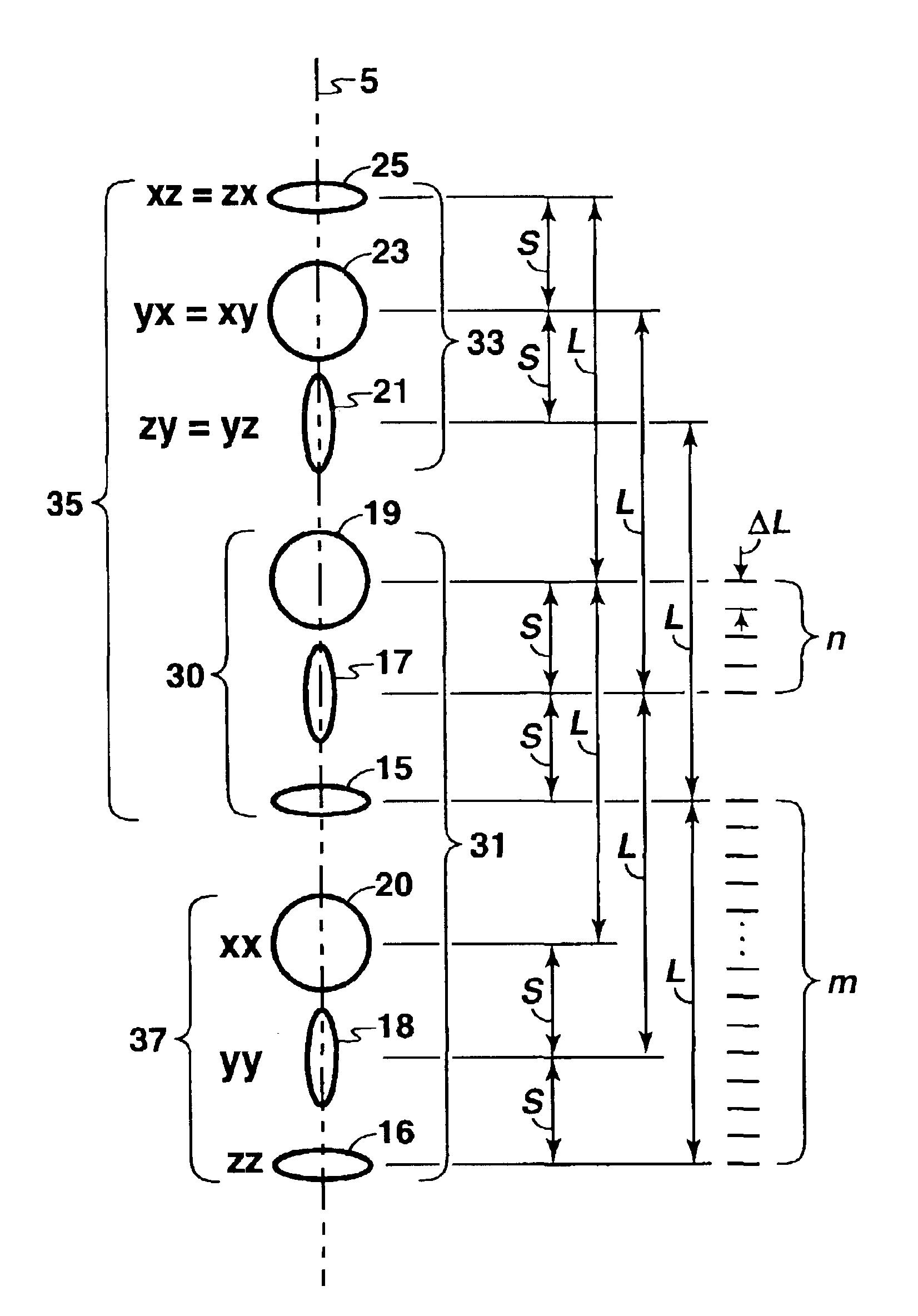
[0065]To construct a proper magnetic induction tensor at each point in the formation, it is necessary to periodically sample and save for later use the responses of the arrays. As illustrated in FIG. 5, the arrays are oriented coaxially with the logging instrument axis 5. The cross-coupled array 33 (assumed for specificity of this discussion to be the upper array) responses are sampled and stored for later use. Since the instrument is moving up the borehole 64 axis (the usual direction in wireline logging operations) the transmitter array 30 will eventually occupy the same position 63 that the upper receiver array occupied when the upper receiver array data was sampled and stored.

[0066]The choice of spatial sampling rate (or interval) discussed above will guarantee that the instrument's (direct-coupled) responses 37 are sampled at points appropriate to combine with the previously sampled cross-coupled signals. The previously sampled cross-coupled signals were sampled at the same poi...


PUM


Abstract

An apparatus and a method for recording the magnetic induction tensor induced in an earth formation are provided. The apparatus includes a magnetic induction device having at least three mutually orthogonal transmitter dipoles and at least three mutually orthogonal receiver dipoles that are direct-coupled, and at least three mutually orthogonal receiver dipoles that are cross-coupled. The method includes using the apparatus to sample the magnetic induction tensor components at a point. Further, samples may be taken at regularly spaced intervals using the magnetic induction device, moving the triaxial logging unit so that each transmitter and each receiver sequentially occupy the same point, repeating these steps until each transmitter and receiver array have sequentially occupied all desired points, and combining the magnetic induction tensor components to form the magnetic induction tensor. These components are useful in inferring water saturation and estimating hydrocarbon volumes in petroleum reservoirs.

Description

[0001]This application claims the benefit of U.S. Provisional Application No. 60 / 394,813 filed on Jul. 10, 2002.FIELD OF THE INVENTION[0002]This invention is related generally to the field of electromagnetic induction logging instruments. More specifically, the invention is related to an apparatus and a method for electromagnetic resistivity logging in electrically anisotropic media using mutually orthogonal magnetic dipole transmitters and mutually orthogonal magnetic dipole receivers.BACKGROUND OF THE INVENTION[0003]The amount of oil and / or gas in a subterranean reservoir will determine whether developing the reservoir and bringing the oil or gas to the surface is economical. Sedimentary reservoir rocks comprise a porous medium. The pore spaces in these rocks are typically fluid-filled, usually with a brine that is electrically conductive and relatively dense. Hydrocarbon fluids are electrically resistive and less dense than brine. During hydrocarbon emplacement in the pore spaces...

Claims


Application Information

Patent Timeline
IPC IPC(8): G01V3/28G01V3/18
CPCG01V3/28Y02A90/30
Inventor KENNEDY, W. DAVID
Owner EXXONMOBIL UPSTREAM RES CO
Why Eureka
Try Eureka