Heat exchanger cleaning process

a technology of heat exchanger and cleaning process, which is applied in the direction of flush cleaning, lighting and heating apparatus, cleaning using liquids, etc., can solve the problems of affecting the efficiency of heat exchange equipment, and no realistic alternative was available for cleaning heat exchange equipment without stopping the process, etc., to achieve accurate control of the volumetric ratio of chemical vapor and steam

Inactive Publication Date: 2005-08-30
REFINED TECH
View PDF8 Cites 23 Cited by
  • Summary
  • Abstract
  • Description
  • Claims
  • Application Information

AI Technical Summary

Problems solved by technology

Much of this consumption is due solely to the fouling of system components.
This tendency to deposit exacerbates an already difficult situation.
As an example, in an article published in Chemical Engineering Progress, a heat exchanger fouling rate of 0.35 yr-1 was used which when applied to a particular piece of equipment may cause an annual efficiency penalty of 30%.
However, prior to this invention, no realistic alternative was available for cleaning heat exchange equipment without stopping the process for a substantial amount of time, subjecting the equipment to metal deteriorating chemistry and deleterious thermal cycles.
Typically, refiners will continue to operate these exchangers—despite a 30% annual reduction in efficiency—until the plant is shut down for major maintenance because the cost to shut down the facility and clean the exchangers is too great.
During the prior art procedures, exchangers are subjected to corrosive chemicals, abrasive procedures and large thermal excursions, all of which may damage the equipment or make it impossible to reassemble.
Five days of crude unit shutdown may cause a facility to irreversibly lose more than $10 million in revenue.
Historically, using prior art practices, this loss in revenue was more costly than the savings provided from cleaning.
Other problems with the prior art systems are environmental in nature.
The inefficiency caused by fouling causes the emissions of carbon dioxide, sulfur dioxide, nitrogen oxide and other gases to be increased.
The prior art methods also produce large quantities of hazardous waste.
A typical refinery turnaround using this kind of water-circulation cleaning procedure will produce approximately 500,000 gallons of hazardous material that must be disposed of at high cost to the refinery while creating a potential ecological nuisance.
Likewise, another prior art procedure of blasting solid contaminant from the exchanger using high pressure water also produces large quantities of solid hazardous waste that must be specially treated.
These methods further require the vessel to be sealed under pressure and to cool—a technique that has been known to occasionally cause catastrophic collapse.

Method used


Image

  • Heat exchanger cleaning process
  • Heat exchanger cleaning process
  • Heat exchanger cleaning process

Examples


Embodiment Construction

[0020]The present invention solves the problems present in the prior art methods.

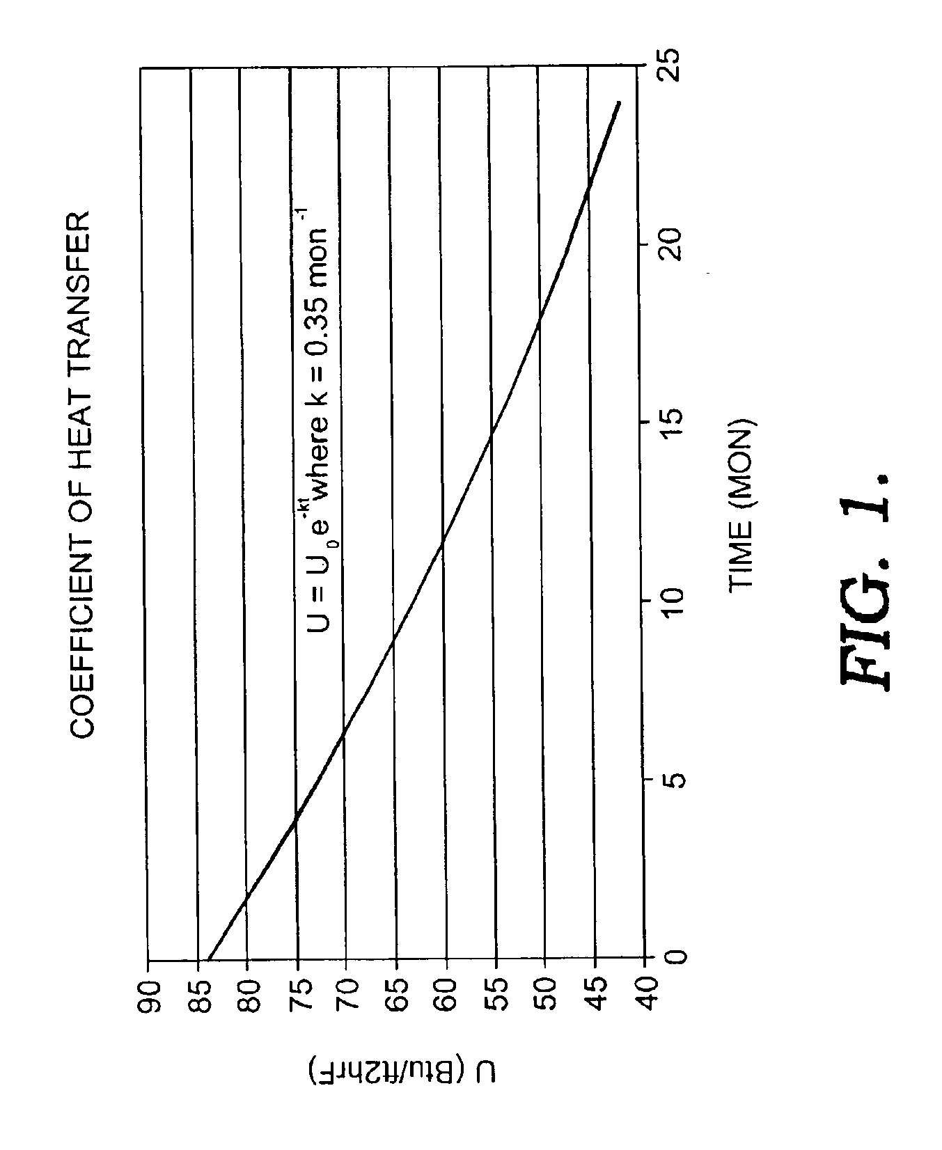
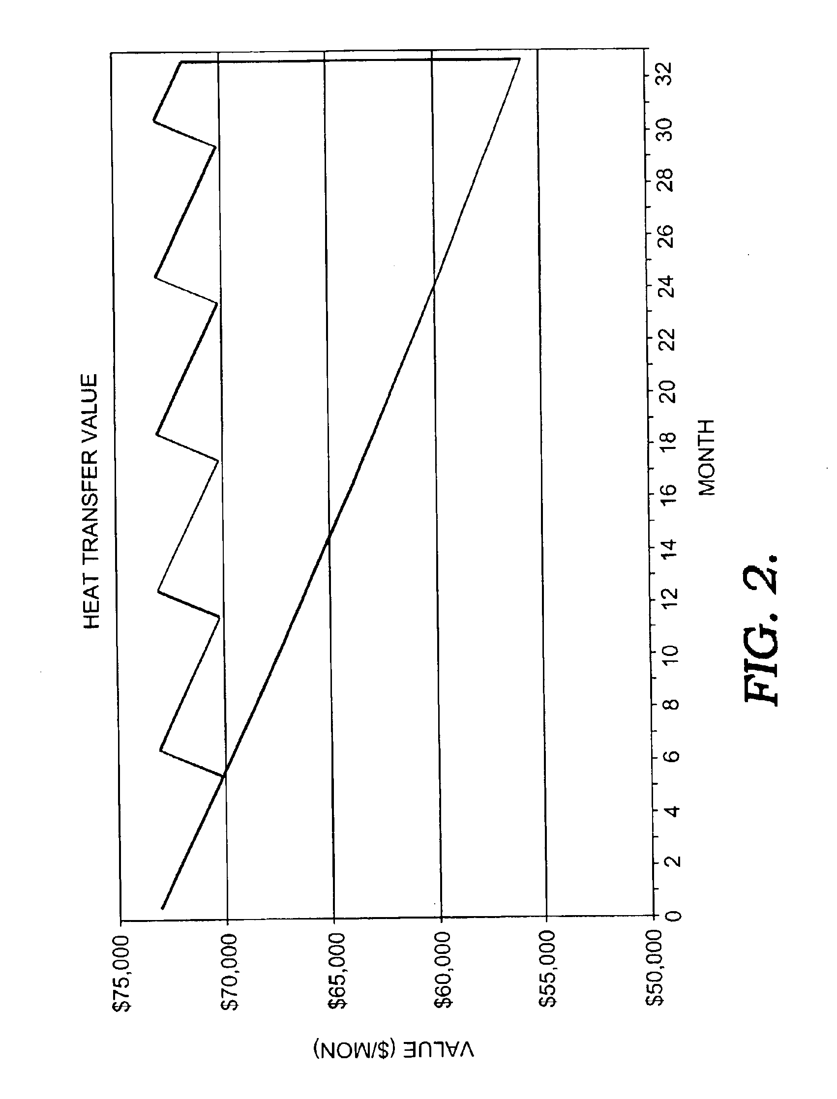
[0021]First, by enabling the exchangers to be cleaned more regularly, the resulting unfouled exchangers operate more efficiently, with less heat input. Thus, operating expense is reduced. FIG. 2 shows how operating expense is reduced when a regular maintenance program using the disclosed process is established—the area below a curve computed using a regular cleaning regimen and above the curve without a cleaning regimen. A basic net present value calculation can be used to determine a most optimal cleaning cycle. A curve that identifies a 6 month period as the optimal cleaning interval when comparing cost to clean versus loss in efficiency is shown in FIG. 4. This interval is much shorter than before possible with the prior art methods in which delays of 24 months are typical.

[0022]Regular cleaning is possible because the present invention enables the exchangers to be cleaned much more quickly than with...


PUM

PropertyMeasurementUnit
temperaturesaaaaaaaaaa

Abstract

Disclosed is a novel process for cleaning and restoring the operating efficiency of organic liquid chemical exchangers in a safe and effective manner and in a very short period of time, without a need to disassemble the equipment and without the need to rinse contaminate from the equipment after cleaning. Used is a formulation of monocyclic saturated terpene mixed with a non-ionic surfactant package specifically suited to oil rinsing. The terpene-based chemical is injected into organically contaminated exchangers using a novel process involving high-pressure steam to form a very effective cleaning vapor.

Description

CROSS-REFERENCE TO RELATED APPLICATIONS[0001]None.STATEMENT REGARDING FEDERALLY SPONSORED RESEARCH OR DEVELOPMENT[0002]None.BACKGROUND OF THE INVENTION[0003]This invention relates to a process for cleaning the metal surfaces of organically contaminated heat transfer equipment in the petroleum and petrochemical industries to quickly, safely, and economically.[0004]The manufacture of chemicals and petroleum products in the field of this invention consumes enormous amounts of energy. One major refiner—Exxon Mobil—estimates that it expends $190 million dollars in energy per month to operate its refineries and chemical facilities. See The Lamp, Exxon Mobil, Winter 2002. Exxon Mobil production constitutes approximately 10.6% of the United States production capability. Accordingly, one would estimate that more than $1.7 billion dollars of energy is consumed per month in producing these organic products in the petroleum refining industry.[0005]Much of this consumption is due solely to the f...

Claims


Application Information

Patent Timeline
Patent Type & Authority Patents(United States)
IPC IPC(8): B08B9/02C11D3/20C11D1/72C11D1/38C11D1/52C11D11/00C11D3/43C11D3/18F28G9/00
CPCB08B9/00B08B9/032C11D1/52C11D1/72C11D3/188C11D3/2037C11D3/2062C11D3/43C11D11/0041F28G9/00B08B2230/01
Inventor JANSEN, BRUCE ROBERTSEARS, SEAN EDWARD
Owner REFINED TECH
Why Eureka
Try Eureka