Motor vehicle door lock with an electromechanical central locking system drive

a technology of electromechanical and central locking system, which is applied in the direction of motor/generator/converter stopper, dynamo-electric converter control, lock application, etc., can solve the problems of inherently too fast and powerful central locking system drive, insufficient block current limitation,

Inactive Publication Date: 2005-08-30
BROSE SCHLIESSSYSTEME GMBH & CO KG
View PDF30 Cites 14 Cited by
  • Summary
  • Abstract
  • Description
  • Claims
  • Application Information

AI Technical Summary

Benefits of technology

[0013]The motor control which is present anyway is used in accordance with the invention to control the rpm of the electric drive motor. Thus, it is possible to have the electric drive motor, as a whole, run much more slowly than previously conventional. A more slowly running electric drive motor does lead to slower reaction of the mechanisms of the motor vehicle door lock, but enjoys a series of major advantages. First, there is optimum rpm matching over the entire path of motion of the central locking system element. Unnecessarily high acceleration forces are avoided on the levers of the lock mechanism. The slow running speed of the central locking system drive leads to a reduction of noise formation. The blocking operation of the electric drive motor can be easily integrated into the control circuit, and the blocking current can be additionally limited. In particular, in a digital control circuit this function can be accomplished essentially without additional cost, simply in the programming of a microcomputer.
[0015]The central locking system drive according to the invention is moved with a much lower voltage, for example, a voltage of 3 V. With this lower voltage, the central locking system drive, of course, does not have the torque necessary for overcoming additional counterforces. The control of the rpm of the electric drive motor provided in accordance with the invention now leads to the power supply voltage increasing in reaction to the load and when the load is removed, it is reduced again. Overall, the central locking system drive thus runs more slowly and less powerfully, but for this reason much more quietly.
[0019]The control which has been described above for automatic actuation of the electric drive motor can also be selectively actuated when the electric drive motor is manually triggered from the interior of the motor vehicle, for example, with the locking button for general locking of the motor vehicle or with a locking button or the like for triggering the child safety. Within the motor vehicle, specifically also for manual triggering, the noise development of the motor vehicle door lock is perceived as stronger than from the outside. Accordingly, it is perceived as comfortable and pleasant even if, in this case, the operation of the central locking system drive is quiet.

Problems solved by technology

The blocking operation of the electric drive motor can be easily integrated into the control circuit, and the blocking current can be additionally limited.
In other words, this means that, in the normal case, the central locking system drive inherently works too quickly and powerfully and especially travels into the block.

Method used


Image

  • Motor vehicle door lock with an electromechanical central locking system drive
  • Motor vehicle door lock with an electromechanical central locking system drive

Examples


Embodiment Construction

[0025]Some explanations to which reference should be made here can be found in the Background part of the specification pertaining to the basic structure of a motor vehicle door lock with a central locking system drive, to which the teaching of this invention relates.

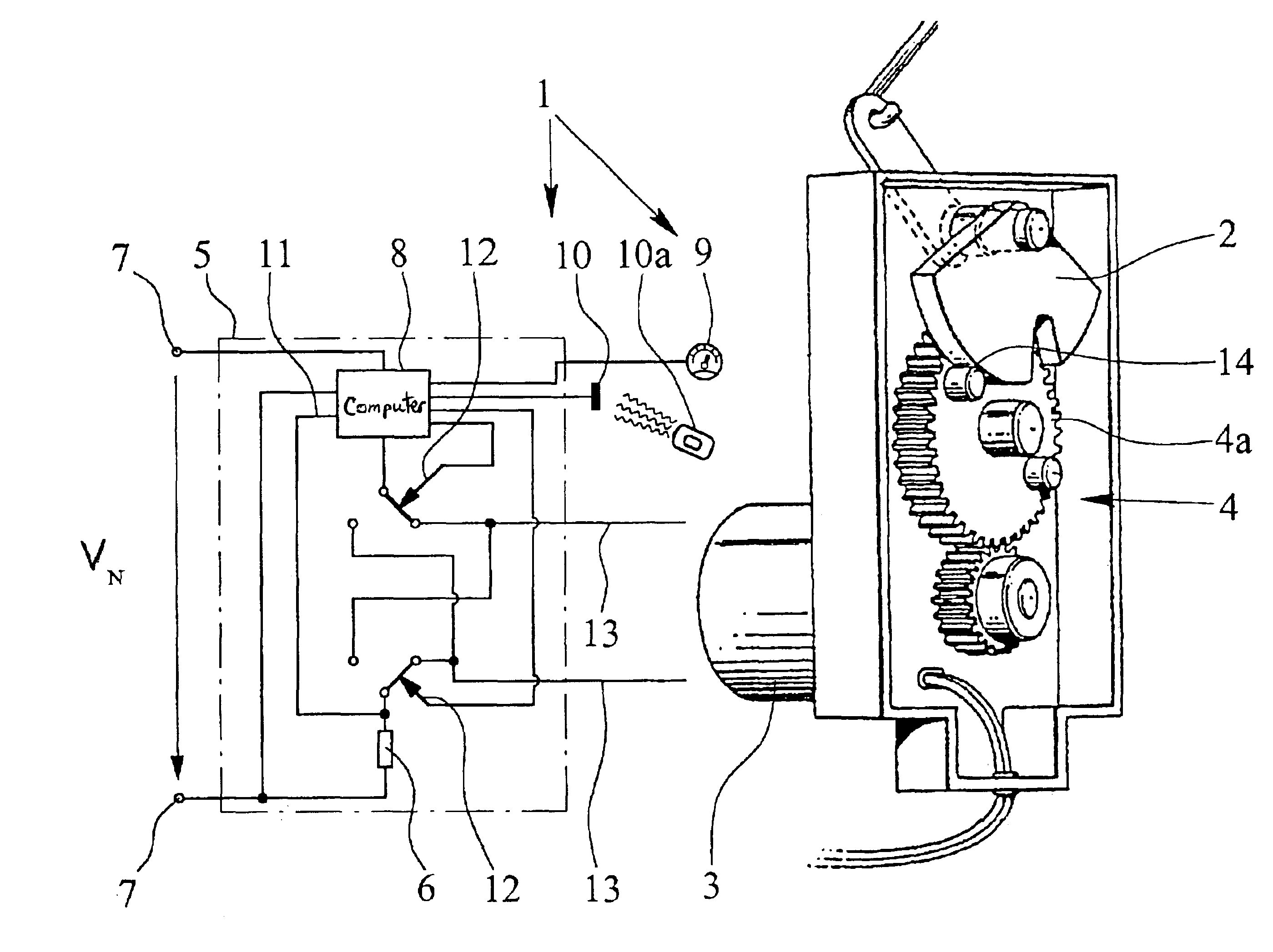
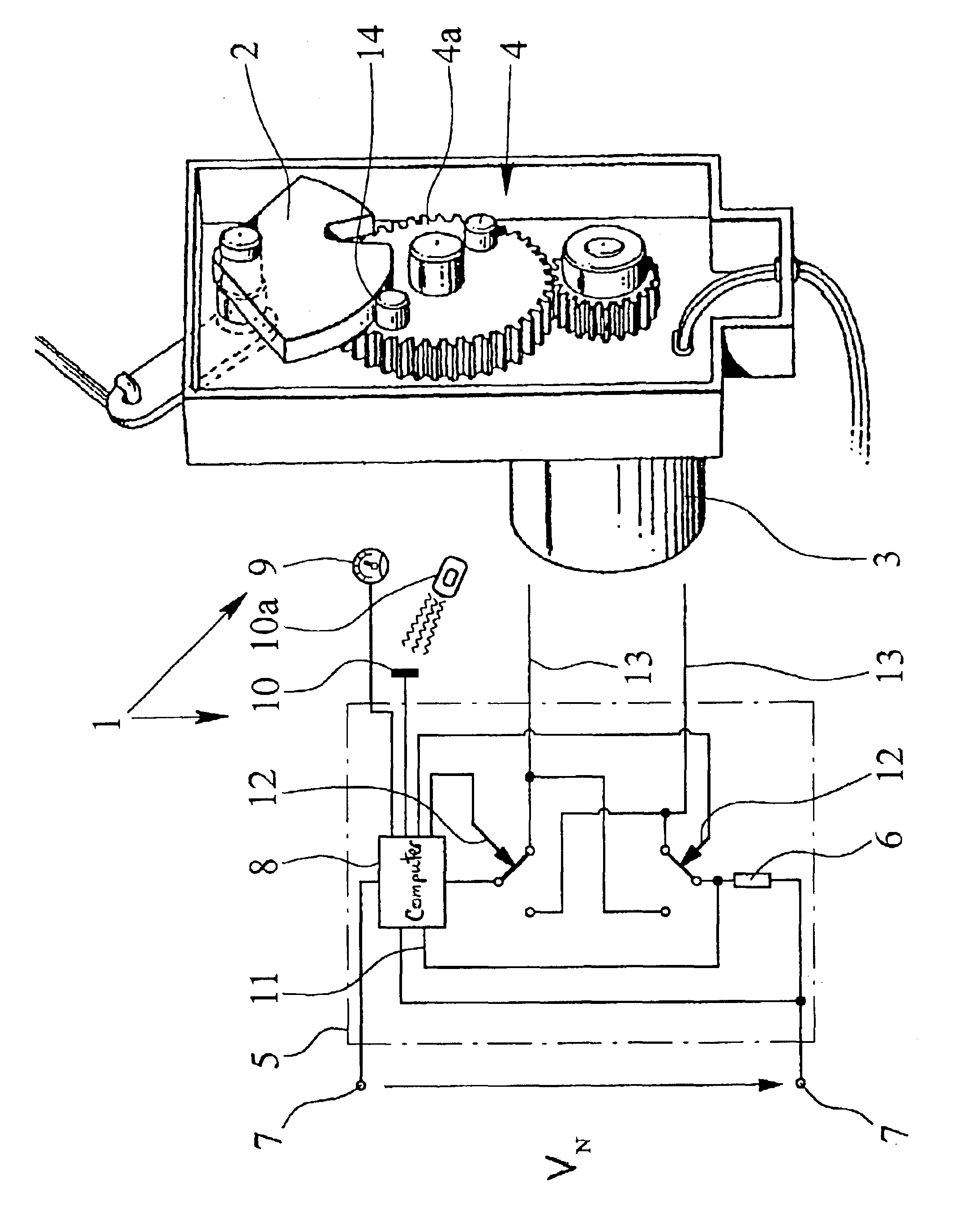
[0026]The teaching of the invention relates to a motor vehicle door lock with an electromechanical central locking system drive 1 and a mechanical central locking system element 2 which is driven by it. In the embodiment shown in the FIGURE, the central locking system drive 1 has an electric drive motor 3 which drives the mechanical central locking system element 2, which is made here as a pivot lever, via a step-down gear, which is made here as toothed gearing 4. There are a host of other structures for electric drive motors 3 with step-down gearing 4, for example, a worm gear pair, spur / bevel wheel gear, and partially coupled to it, spindle / spindle nut gear. Reference should be made to the prior art in this regard, wh...


PUM


Abstract

A motor vehicle door lock with an electromechanical central locking system drive (1) and a mechanical central locking system element (2) driven by it, the central locking system drive (1) having an electric drive motor (3) and a motor control (5) with a motor state sensor (6). The central locking system element (2) can be moved by the central locking system drive (1) at least into a locked position and the motor control (5) is designed such that it triggers the electric drive motor (3) for driving the central locking system element (2) into the locked position after receiving an actuation signal from an actuation unit, such as a closing cylinder, a locking button, a remote control receiving unit or a handle (inside door handle, outside door handle). Preferably, the motor control 5 is also designed such that it automatically triggers the electric drive motor (3) for driving the central locking system element (2) into the locked position as soon as a certain operating state of the motor vehicle has been reached. Furthermore, significantly, the motor control (5) has a control circuit that includes the motor state sensor (6) and this control circuit is designed such that, when the electric drive motor (3) is triggered, the electric drive motor (3) runs with a low rpm that is controlled using the signal of the motor state sensor (6).

Description

BACKGROUND OF THE INVENTION[0001]1. Field of the Invention[0002]The invention relates to a motor vehicle door lock with an electromechanical central locking system drive.[0003]2. Description of Related Art[0004]A conventional motor vehicle door lock of the type under consideration, therefore the lock for a motor vehicle side door, a rear hatch or a rear door, but also for a sliding door of a motor vehicle, generally has locking elements, such as a latch and ratchet, and a lock mechanism with various levers which are used for actuation. In particular, reference can be made to the prior art (for example, published German Patent Application DE 100 06 765 A1 and corresponding U.S. Pat. No. 5,673,578).[0005]Motor vehicle door locks with an electromechanical central locking system drive (for example, German Patent Application DE 100 06 765 A1 and corresponding U.S. Pat. No. 5,673,578) are common. It generally drives a mechanical central locking system element of the lock mechanism in orde...

Claims


Application Information

Patent Timeline
Patent Type & Authority Patents(United States)
IPC IPC(8): E05B65/12E05B65/20E05B17/00E05B65/42E05B47/00E05B77/54
CPCE05B81/06E05B81/64E05B81/62E05B81/16E05B81/25E05B81/34E05B77/36E05B77/26E05B77/54Y10T292/1082
Inventor KACHOUH, CHECRALLAHBARTEL, PETERHENTSCH, INGMAR
Owner BROSE SCHLIESSSYSTEME GMBH & CO KG
Why Eureka
Try Eureka