
Apparatus and methods for heat loss pressure measurement

a technology of apparatus and pressure measurement, applied in the direction of heat measurement, fluid pressure measurement, instruments, etc., can solve the problems of inability to accurately measure pressure, large design complexity, and electrical imbalance of bridges, and achieve the effect of improving the range of accurate pressure measurement and improving the accuracy of low, mid-range and high pressure measuremen

Inactive Publication Date: 2005-09-06
MKS INSTR INC
View PDF40 Cites 6 Cited by
  • Summary
  • Abstract
  • Description
  • Claims
  • Application Information

AI Technical Summary

Benefits of technology

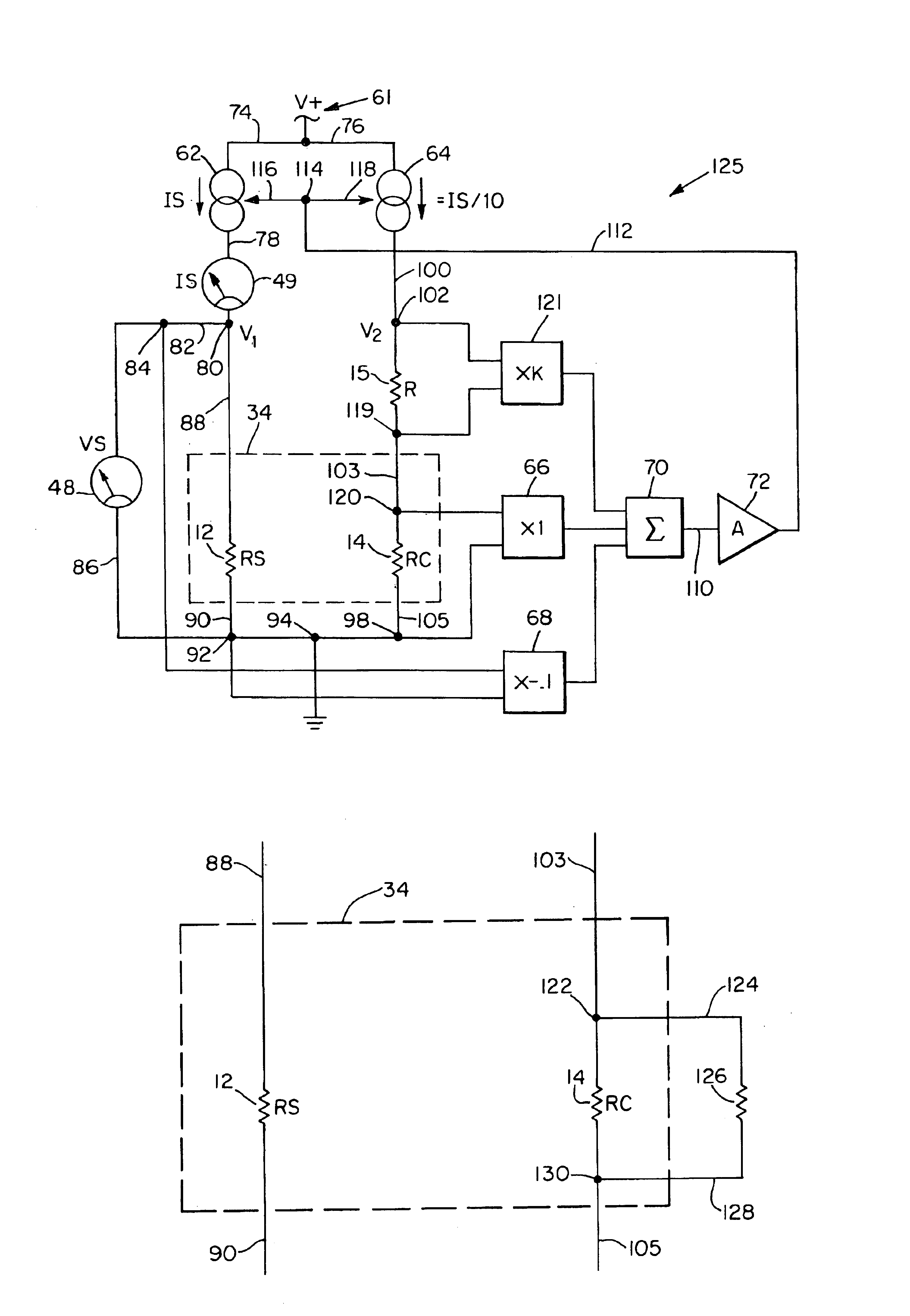
[0044]The present invention provides improvements for heat loss pressure measurement which cooperate synergistically to provide significantly improved low, mid-range and high pressure measurement accuracy, thus, permitting the range of accurate pressure measurement to be extended to lower and to higher pressures within a single gauge.
[0045]As a first improvement, a small diameter wire sensing element is positioned in the same plane as and spaced from a small diameter wire compensating element with two parallel flat thermally conductive plates, each spaced 15 microns from the sensing and compensating elements. In this manner, the inventors have achieved high relative sensitivity in simple geometry without relying on convection. The extreme complexity and cost of microminiature Pirani gauge designs and the several disadvantages of convection cooling of the sensing element are simultaneously avoided.
[0046]The inventors have found that this extremely simple, small, and inexpensive measuring means gives results up to atmospheric pressure comparable to those obtained with very complex microminiature Pirani gauges and to those obtained with much larger, position-sensitive convection-cooled Pirani gauges. Surprisingly, this improvement also provides a sensing element with a volume of only 3% that of the sensing element in the microminiature Alvesteffer gauge. The compensating element in the new device has a volume of less than 0.5% of the Alvesteffer-type compensating element.
[0047]The present invention also provides improved temperature correction. The inventors have found that the accuracy of low pressure measurement can be significantly improved by better maintaining constant the temperature gradient γ at the ends of the sensing element (see Eqs. 10 and 11). The inventors have found that constancy of γ can be achieved by simultaneously:
[0054]In this manner, the present invention provides significant advancements in Pirani gauge accuracy, production cost, and package size.

Problems solved by technology

In these methods, an electrical imbalance of the bridge is created which reflects gas pressure.
However, existing designs leave much to be desired for accurate pressure measurement, especially at lower pressures.
There are a number of problems with previous attempts to develop microminiature gauges.
Although microminiature sensors provide good sensitivity over a large pressure range independent of orientation, their design is extremely complex and fabrication requires numerous elaborate processing steps in highly specialized equipment costing hundreds of thousands of dollars.
Microminiature sensors suffer from the same type of ambient temperature-caused errors as do macroscopic sensors.
Thus, any attempt at pressure measurement with a Pirani gauge without temperature correction will be confused by non-pressure dependent power losses caused by changes in ambient temperature.
However, at other pressures this means of temperature compensation is not very effective.
However, this technique (using two or more materials in R2 having different temperature coefficients of resistance to approximate the temperature coefficient of RS) is effective only over a narrow range of pressure.
The inventors have also found, through extensive computer simulation, that using equal temperature coefficients for RS and R2 as recommended by Leck and as practiced in the prior art does not provide an entirely accurate temperature compensation.
Therefore, temperature change effects in prior art Pirani Gauges are especially troublesome at very low pressures where gas conduction losses are very low.
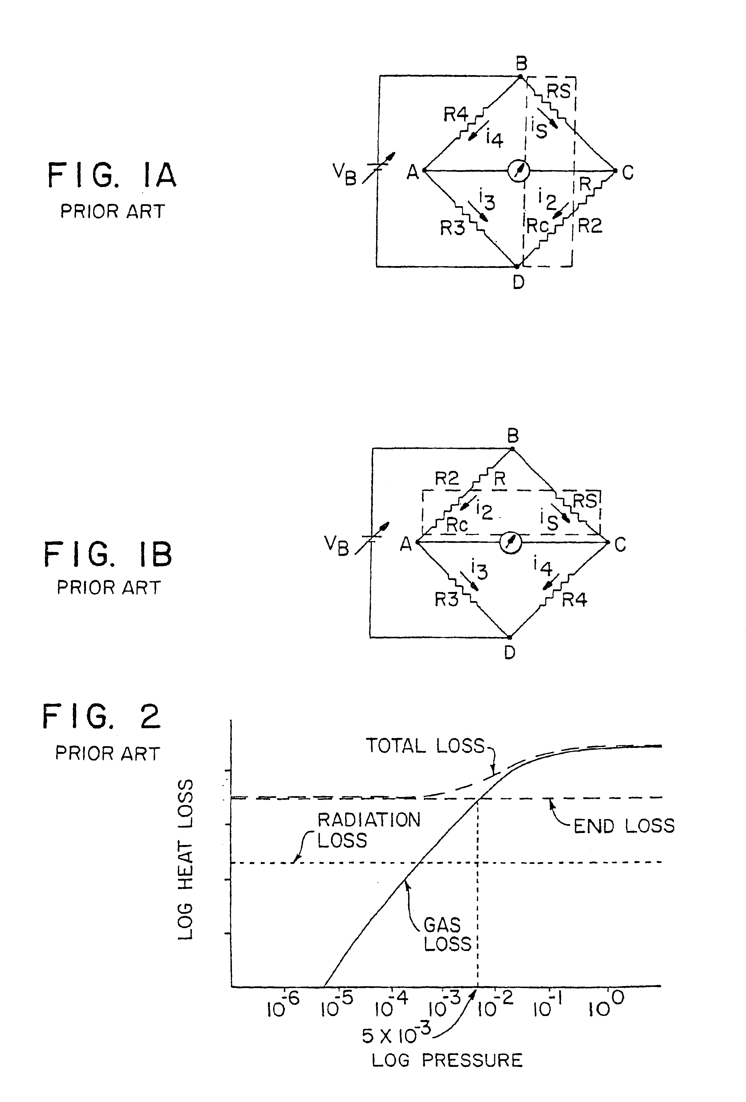
Prior art heat loss gauges cannot measure very low pressures accurately, for example, 1×10⁻⁵ Torr.
The inventors have discovered that this limitation is a result of failure to maintain end losses in the sensing element sufficiently constant when ambient temperature changes.
The Alvesteffer-type Pirani gauge has the capability of indicating pressure in the 10−5 Torr range, but does not provide an accurate indication within that range.
The following analysis shows why prior art designs are ill-suited to correct adequately for ambient temperature changes at low pressures.
This is because at ambient temperature and low pressures, radiation and gas conduction are very inefficient means of exchanging heat from the compensating element to its surroundings relative to heat conduction through the ends of the compensating element.
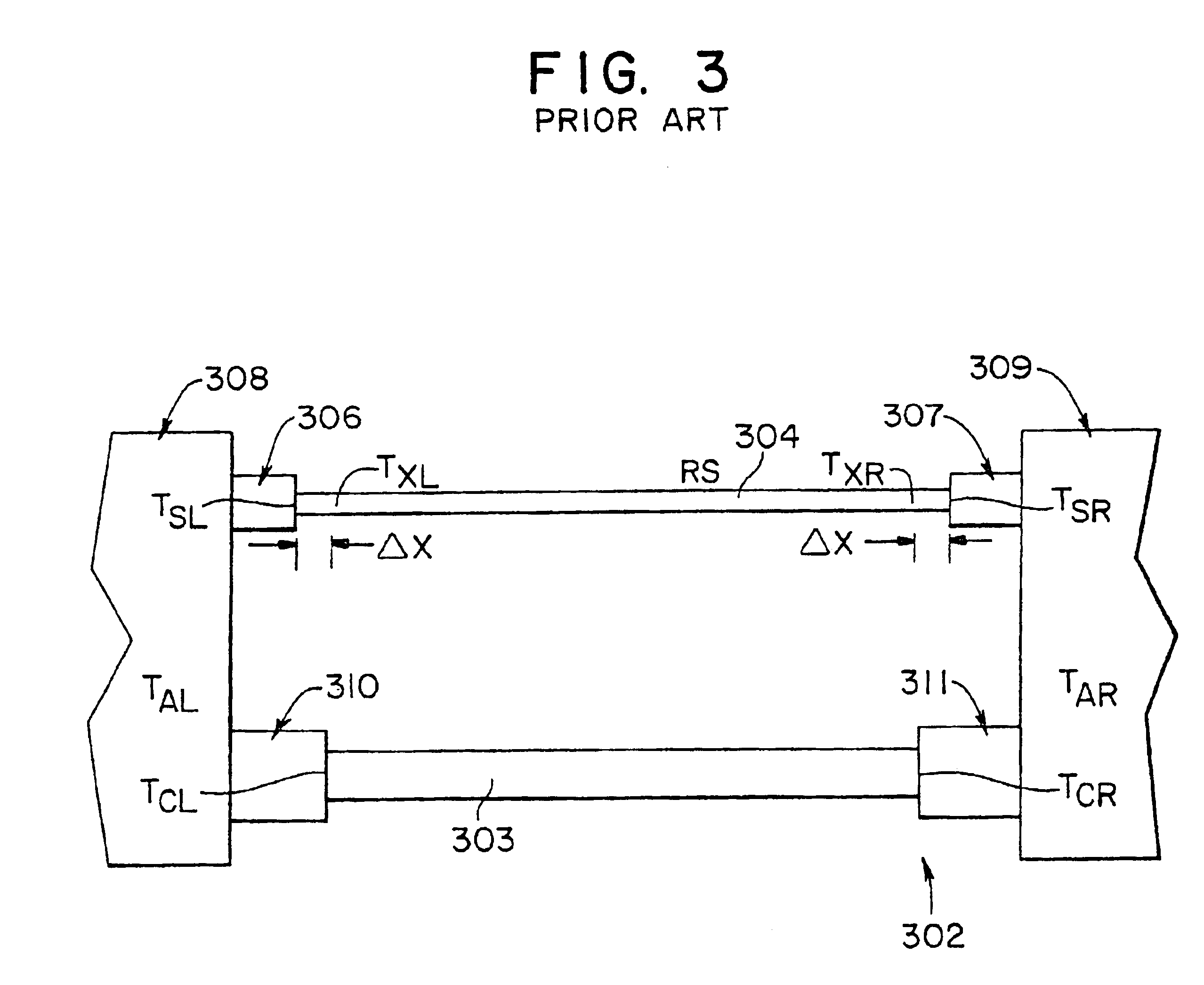
If γL and or γR vary for any reason, then the end losses will change and the pressure indication will be erroneous.
However, the increase in TAR will cause TCR to increase by conduction of heat through the connection.
Prior art Pirani gauges have not been specifically designed to maintain TAL=TAR to the degree necessary for accurate low pressure measurement.
Thus, γL and γR will continually change during the lag time, producing errors in low pressure indication.
Another significant deficiency arises (as the inventors have discovered) from differences in mass between the compensating element and the sensing element.
Thus, γL and γR will change during the lag time, sensing element end losses will not remain constant, and errors will be produced in low pressure measurement.
The same type of problems occur if the compensating element is designed to change temperature at a different rate than does the sensing element with change in ambient temperature at bridge balance.
Prior art designs such as the Alvesteffer-type device have this deficiency.
Yet, prior art Pirani gauges have not been designed to meet this requirement.
As a third problem with prior art gauge designs, the inventors have found that the level of power dissipation in R2 adversely affects accuracy.
As noted above, different physical dimensions for the sensing and compensating elements cause measurement errors when ambient temperature changes.
A fourth problem is that prior art Pirani gauges produce shifts in pressure indications at low pressures when ambient temperature changes.
Although each of these prior art hardware fixes remove some of the errors caused by changes in ambient temperature, none of them removes substantially all of the errors.
Thus prior art Pirani gauges produce significant shifts in pressure indications at low pressures when ambient temperature changes.
However, this system has increased complexity because of the need to measure temperatures or other values.

Method used


Image

  • Apparatus and methods for heat loss pressure measurement
  • Apparatus and methods for heat loss pressure measurement
  • Apparatus and methods for heat loss pressure measurement

Examples


Embodiment Construction

[0069]A description of preferred embodiments of the invention follows. The invention is first described in terms of four categories of improvements to conventional Pirani gauge designs. In a particularly preferred embodiment, the four improvements are used together, and combine synergistically to provide a Pirani gauge having substantially improved performance characteristics. Additional embodiments of the present invention are then described thereafter.

Improvement 1

[0070]The first category of improvements will be discussed with reference to FIGS. 4a and 4b. FIG. 4a is a side view of a portion 10 of an improved heat loss gauge (not to scale). FIG. 4b is a sectional view of portion 10 taken along line 4b—4b in FIG. 4a. As shown in FIGS. 4a and 4b, a small diameter wire sensing element 12 is located in the same plane and spaced a distance d from a small diameter wire compensating element 14. Spacing d between sensing element 12 and compensating element 14 is preferably approximately 0...


PUM

PropertyMeasurementUnit
voltageaaaaaaaaaa
pressureaaaaaaaaaa
pressureaaaaaaaaaa

Abstract

A heat loss gauge for measuring gas pressure in an environment includes a resistive sensing element and a resistive compensating element. The resistive compensating element is in circuit with the sensing element and is exposed to a substantially matching environment. An electrical source is connected to the sensing element and the compensating element for applying current through the elements. The current through the sensing element is substantially greater than the current through the compensating element. Measuring circuitry is connected to the sensing element and the compensating element for determining gas pressure in the environment to which the sensing element and compensating element are exposed based on electrical response of the sensing element and the compensating element.

Description

RELATED APPLICATIONS[0001]This application is a continuation-in-part of U.S. application Ser. No. 09 / 583,339, filed May 31, 2000, now U.S. Pat. No. 6,658,941 which is a continuation-in-part of U.S. application Ser. No. 09 / 475,392, filed Dec. 30, 1999, now U.S. Pat. No. 6,227,056, issued May 8, 2001, which is a Divisional of U.S. application Ser. No. 08 / 897,629, filed Jul. 21, 1997, now U.S. Pat. No. 6,023,979, issued Feb. 15, 2000. The entire teachings of the above applications and patents are incorporated herein by reference.BACKGROUND[0002]Because the rate of heat transfer through a gas is a function of the gas pressure, under certain conditions measurements of heat transfer rates from a heated sensing element to the gas can, with appropriate calibration, be used to determine the gas pressure. This principle is used in the well known Pirani gauge (shown in schematic form in FIGS. 1a and 1b), in which heat loss is measured with a Wheatstone bridge network which serves both to heat ...

Claims


Application Information

Patent Timeline
Patent Type & Authority Patents(United States)
IPC IPC(8): G01L21/00G01L21/12G01L9/02G01L19/04
CPCG01L21/12G01L19/04
Inventor BILLS, DANIEL G.BORENSTEIN, MICHAEL D.
Owner MKS INSTR INC
Learn More