
Dynamotor of hybrid vehicle, and method of control thereof

a hybrid vehicle and dynamo technology, applied in the direction of dynamo-electric converter control, engine starter control, battery/fuel cell control arrangement, etc., can solve the problem of increasing costs that cannot be avoided, and achieve the effect of stable power torque characteristic and power generation characteristic, and ensured high-efficiency control

Inactive Publication Date: 2005-09-06
HITACHI LTD +1
View PDF23 Cites 45 Cited by
  • Summary
  • Abstract
  • Description
  • Claims
  • Application Information

AI Technical Summary

Benefits of technology

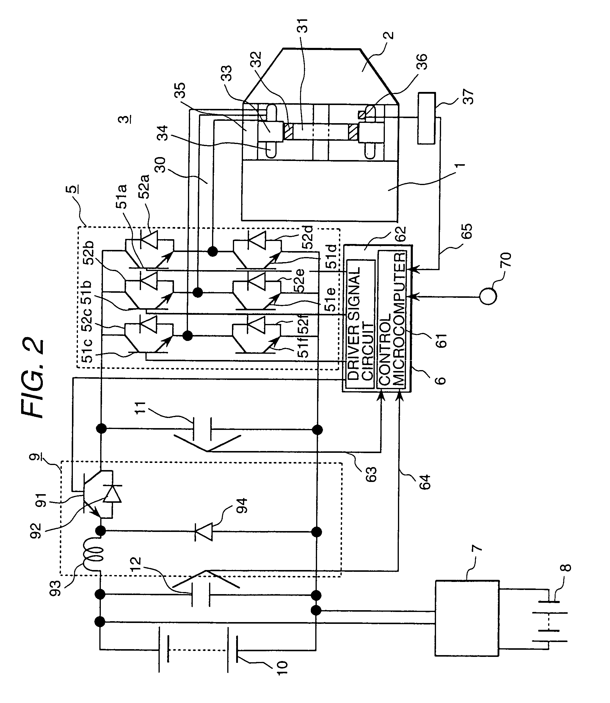
[0020]According to the present invention, when the motor generator is used as a motor to start the internal combustion engine or to provide torque assist, battery voltage is stepped up by the step-up circuit and is applied to the inverter input. At the same time, the inverter provides control to get the rotational speed specified by a command. In other words, the current phase of the stator winding is adjusted and the amount of field magnetic flux component is regulated, thereby obtaining a specified speed, a specified armature current and a specified torque. This allows a high voltage to be obtained by means of a step-up chopper circuit and permits the field current component, hence, starting torque to be increased.

Problems solved by technology

This requires a substantial improvement of a car, and resulting increase in costs cannot be avoided.

Method used


Image

  • Dynamotor of hybrid vehicle, and method of control thereof
  • Dynamotor of hybrid vehicle, and method of control thereof
  • Dynamotor of hybrid vehicle, and method of control thereof

Examples


Embodiment Construction

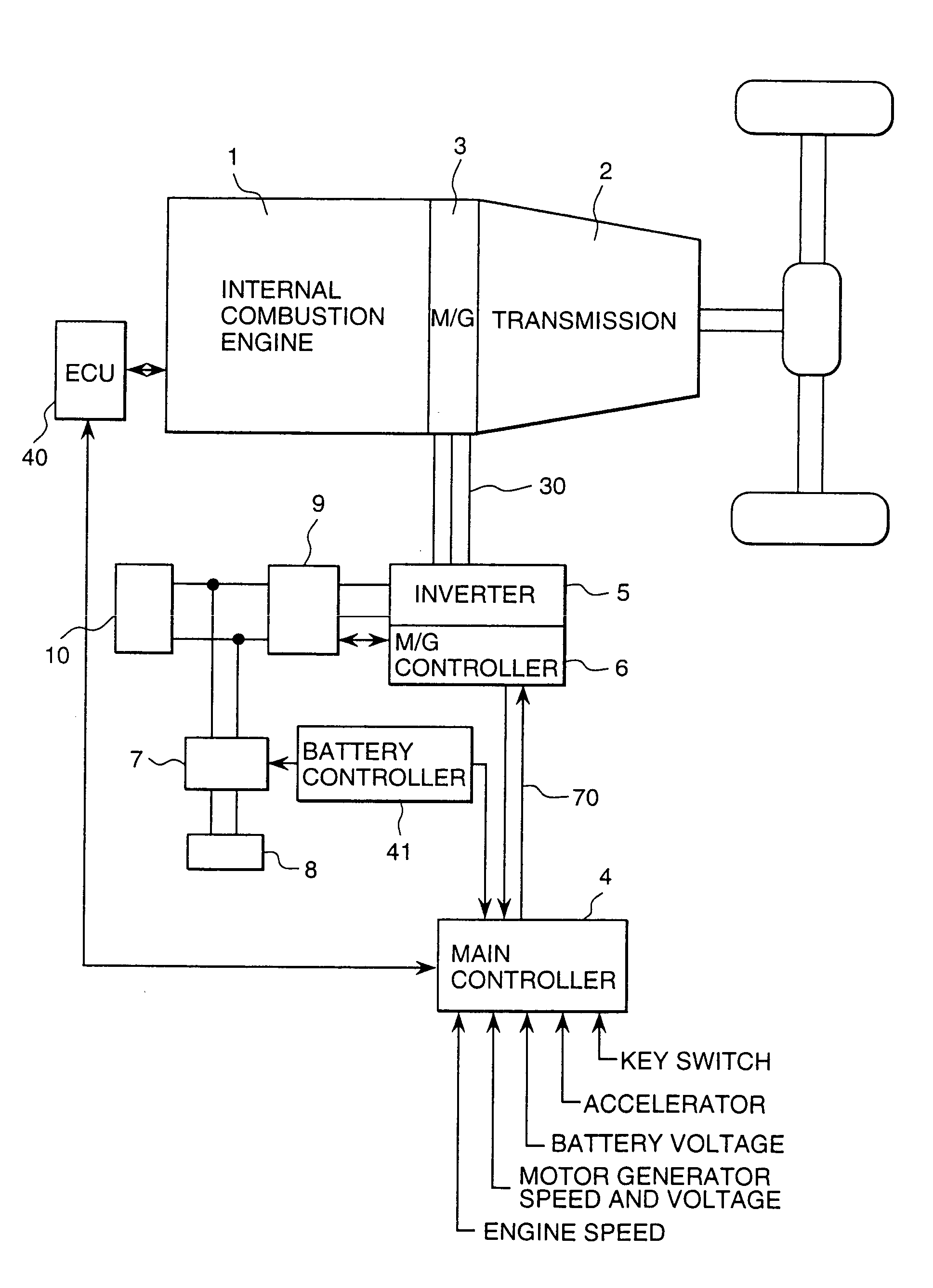
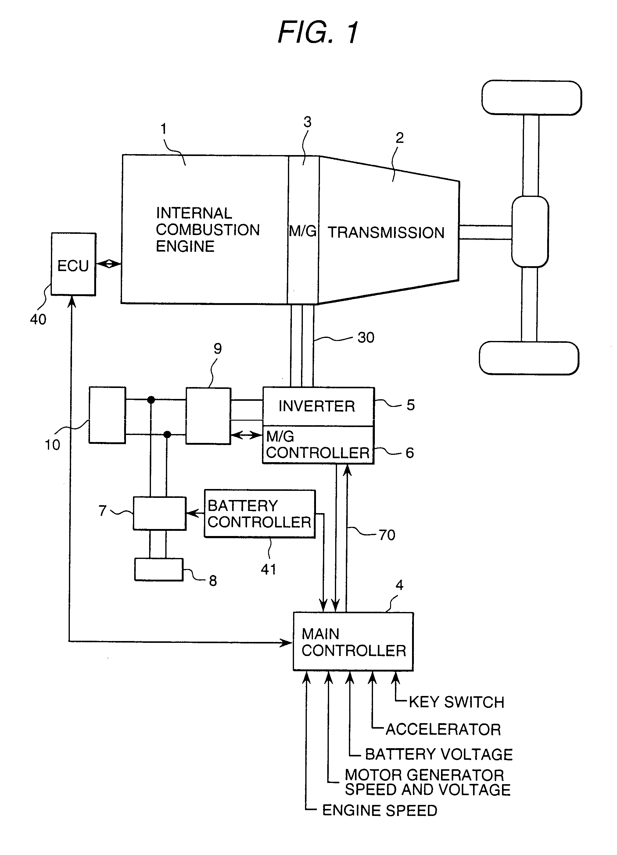
[0035]The following describes embodiments according to the present invention with reference to drawings: FIG. 1 is a block diagram representing the basic configuration of the motor generator system in a hybrid car adopting a permanent magnet field type synchronous motor generator.

[0036]In the motor generator system of FIG. 1, a motor generator 3 drives an internal combustion engine 1 and operates in the generator mode after the internal combustion engine 1 has started. The main battery 10 for high voltage (for example, 42-volt system) is charged with generated power. In this configuration, a motor generator 3 of flat structure is installed between the internal combustion engine 1 and transmission 2. The motor generator 3 is a permanent magnet field type synchronous motor generator in this case. The output of the motor generator 3 is led to the step-down chopper circuit 9 through the inverter main circuit 5, and the generated voltage is stepped down to reach the level of the specifie...


PUM


Abstract

The present invention is characterized by a hybrid car comprising a motor generator mechanically connected with the crank shaft of an internal combustion engine for driving a car wherein the internal combustion engine is started by electric power supplied by a battery and power is generated by rotation from the internal combustion engine to charge the battery, an inverter for controlling the drive and power generation of the motor generator, and a control circuit for controlling the inverter, this hybrid car further characterized in that the motor generator is driven by battery power to start the internal combustion engine, and after the internal combustion engine has started, the battery is charged by the generator mode operation of the motor generator using the power of the internal combustion engine, wherein a step-down chopper circuit is provided between the battery and the inverter, and step-down control is provided to ensure that the power generation voltage will reach the level of the battery charging voltage through the step-down chopper circuit.

Description

TECHNICAL FIELD[0001]The invention relates to a motor generator and its control method in a hybrid car comprising a motor generator connected to an engine as a drive source, and particularly to a motor generator and its control method capable of controlling the armature current phase and adjusting field current component.BACKGROUND ART[0002]There are two methods for driving a hybrid car according to the prior art: One is a series hybrid method wherein power is obtained by driving a generator by the driving speed of an engine as an internal combustion engine, and this power is used to drive the motor connected to the axle, then a car is driven by the driving force of the motor (Japanese Application Patent Laid-Open Publication No. Hei 08-298696, Japanese Application Patent Laid-Open Publication No. Hei 06-245322 and Official Gazette of U.S. Pat. No. 5,214,358, for example). The other is a parallel hybrid method wherein part of the driving force of the internal combustion engine is co...

Claims


Application Information

Patent Timeline
IPC IPC(8): B60L11/12B60L11/18B60L11/02B60K6/04B60K6/00B60K6/485B60K6/54B60L50/15B60L50/16B60W10/06B60W10/08B60W20/00
CPCB60K6/485B60K6/54B60L11/12B60L11/1851B60W10/06B60W10/08B60W20/00B60L2210/12Y02T10/6226Y02T10/6286Y02T10/7005Y02T10/705Y02T10/7077Y02T10/7233F02N11/04B60L50/15B60L58/10Y02T10/62Y02T10/70Y02T10/72Y02T10/7072B60K2006/268B60K6/46
Inventor TAHARA, KAZUOKIM, HOUNG JOONGENDO, TSUNEHIROMASAKI, RYOSOAJIMA, KOUINNAMI, TOSHIYUKIMASHINO, KEIICHISAKURAI, YOSHIMI
Owner HITACHI LTD
Learn More