Vacuum insulating material and device using the same

a technology of vacuum insulation and material, which is applied in the direction of lighting and heating equipment, household cooling equipment, packaging goods, etc., can solve the problems of inability to use prior art techniques, long time gives users uncomfortable feelings, and inability to meet user needs

Inactive Publication Date: 2005-09-06
PANASONIC CORP
View PDF45 Cites 146 Cited by
  • Summary
  • Abstract
  • Description
  • Claims
  • Application Information

AI Technical Summary

Benefits of technology

[0020]Vacuum heat insulator of the present invention comprises: a core made of a lamination of a plurality of sheets composed of inorganic fibers having 10 μm or smaller in diameter and a composition including SiO2, as a main component, together with Al2O3, CaO, and MgO; an...

Problems solved by technology

Furthermore, as a recently occurring problem in notebook computers, heat generated within a computer is transferred to a surface of the device enclosure, and the heat of the enclosure surface in contact with a user's body for a long time gives an uncomfortable feeling to the user when the surface temperature rises.
However, the above prior art technique has problems such as impairment of work environment due to powdery dust and complication of the manufacturing process, because of its use of fine powder.
The prior art technique has not been employed, however, if the core does not maintain its own shape.
In particular, when a sheet-formed material consisting of inorganic fibers is used as the core, the prior art technique has not been effective to provide the required flexibility since the inorganic fibers are broken by the pressure and the core disintegrates in the compression forming process.
However, these techniques of the prior art were difficult to adapt for practical use, as they have the following problems.
S30-3139, for instance, it is difficult to form the heat insulator into a consistent shape because it is composed solely of glass fiber.
In a case of fabricating a plate-form vacuum heat insulator, it raises a problem requiring an extra man-hour when using the glass fib...

Method used


Image

  • Vacuum insulating material and device using the same
  • Vacuum insulating material and device using the same
  • Vacuum insulating material and device using the same

Examples


first exemplary embodiment

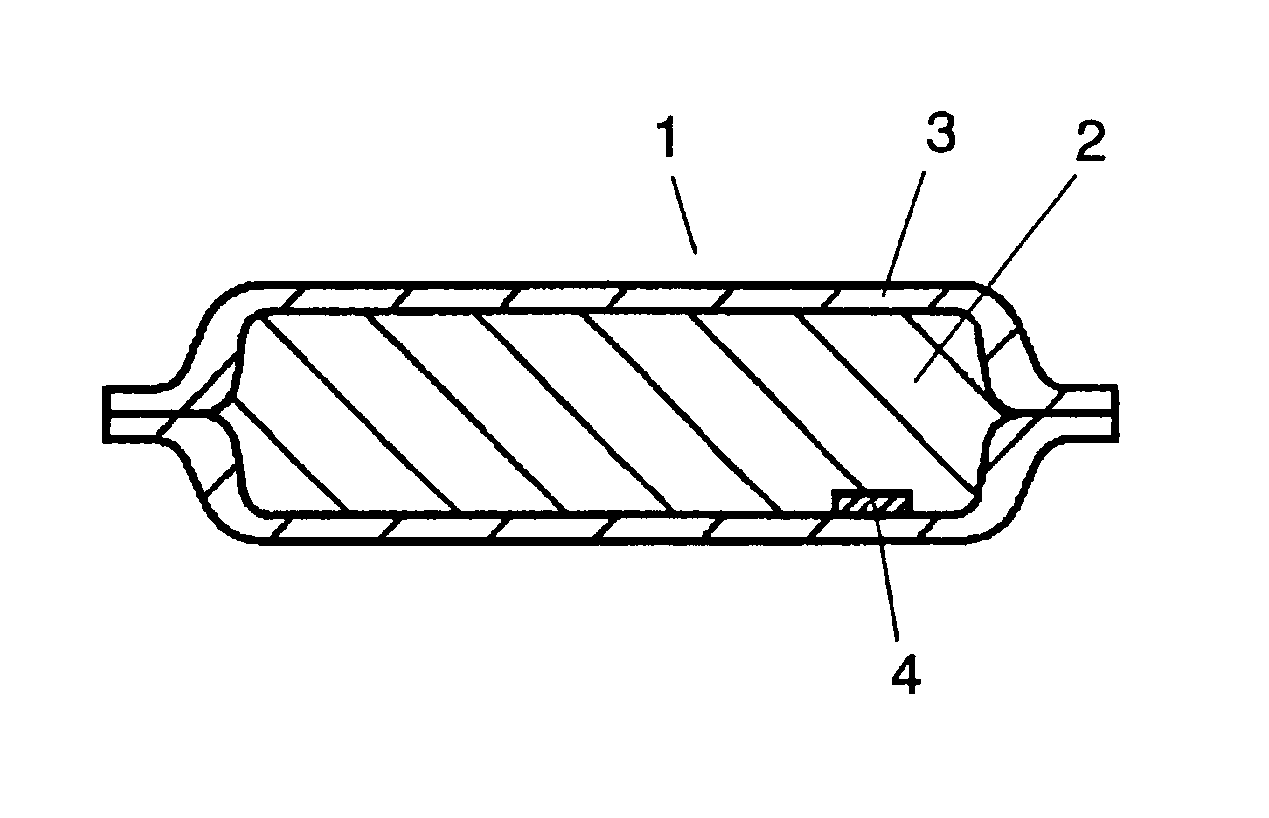
[0039]FIG. 1 shows a sectional view of a vacuum heat insulator in an exemplary embodiment of the present invention, wherein the vacuum heat insulator 1 comprises a core 2, an enveloping member 3, and an absorbent 4.

[0040]The enveloping member 3 comprises two kinds of laminated films.

[0041]One of the laminated films covering one face of the vacuum heat insulator has a four-layer structure comprising polyamide film (16 μm), aluminum foil (6 μm), polyethylene terephthalate film (12 μm), and high density polyethylene film (50 μm). The polyamide film constitutes an outermost layer acting as a surface protective layer, and the high-density polyethylene layer is for a purpose of heat seal.

[0042]Another face consists of a laminated film comprising four layers, i.e. polyamide film (16 μm) as a surface protective layer, a film of ethylene-vinyl alcohol copolymer resin composite (15 μm) with an aluminum layer deposited on its inner surface, polyethylene terephthalate film (12 μm), and high den...

second exemplary embodiment

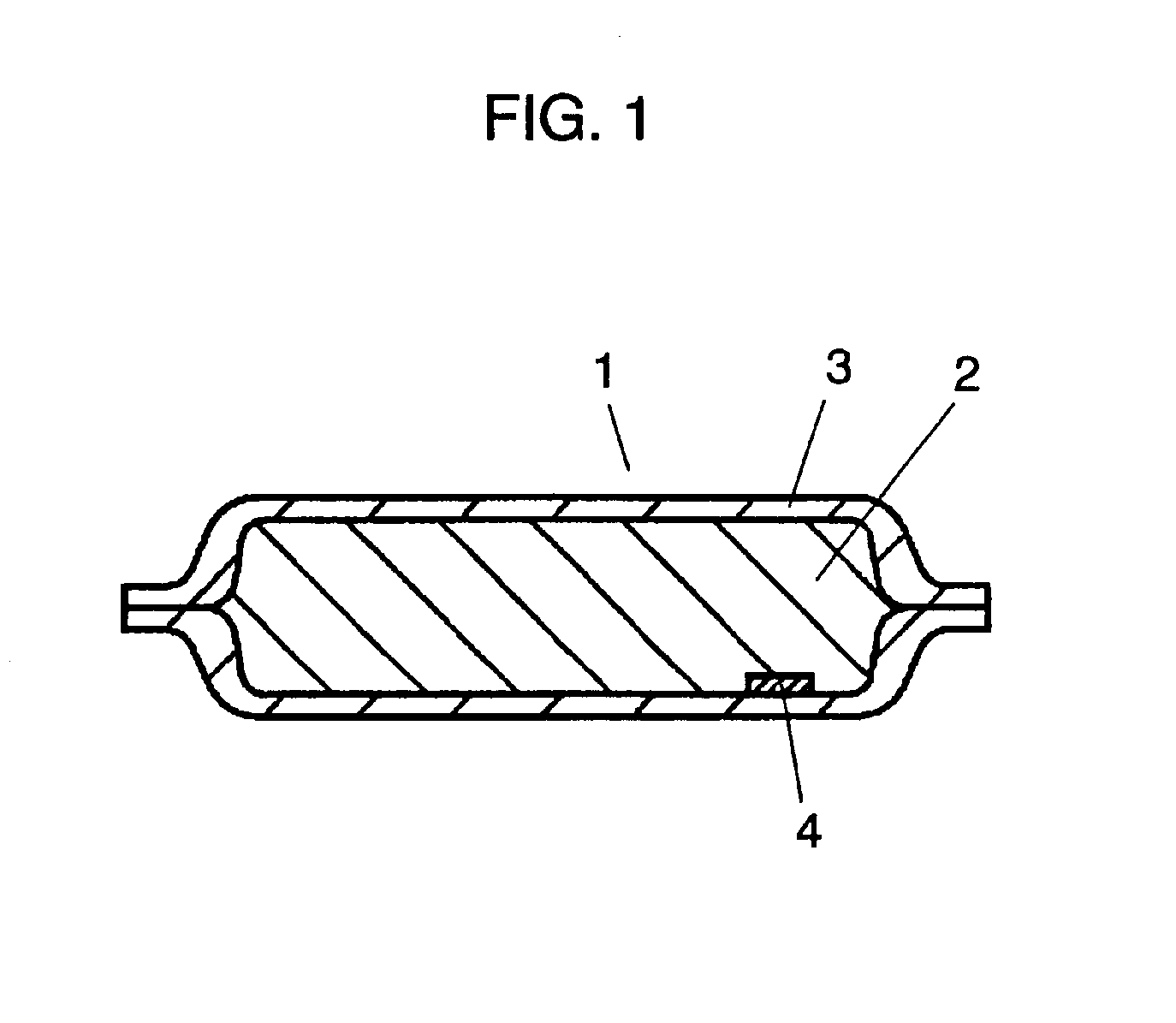
[0075]FIG. 2 is a sectional view of a vacuum heat insulator of the present exemplary embodiment. FIG. 3 is a plan view of the vacuum heat insulator of this exemplary embodiment. In the vacuum heat insulator 1 of the exemplary embodiment, a groove 5 is formed by compression forming.

[0076]A method of fabricating the vacuum heat insulator 1 will be described next.

[0077]In this exemplary embodiment, glass fibers made of silicate glass as a main component and having amorphous structure with an average fiber diameter of 1 to 5 μm is processed into a sheet form at a thickness of 5 mm, for use as a core 2. The core 2 is then constructed by laminating three sheets of the above glass fibers. The vacuum heat insulator 1 is formed by inserting the core into a bag-shaped enveloping member made of a film having a gas barrier property, after the core is drying for one hour at 130° C., evacuating its interior, and hermetically closing its opening by a heat seal.

[0078]Following the above process, th...

third exemplary embodiment

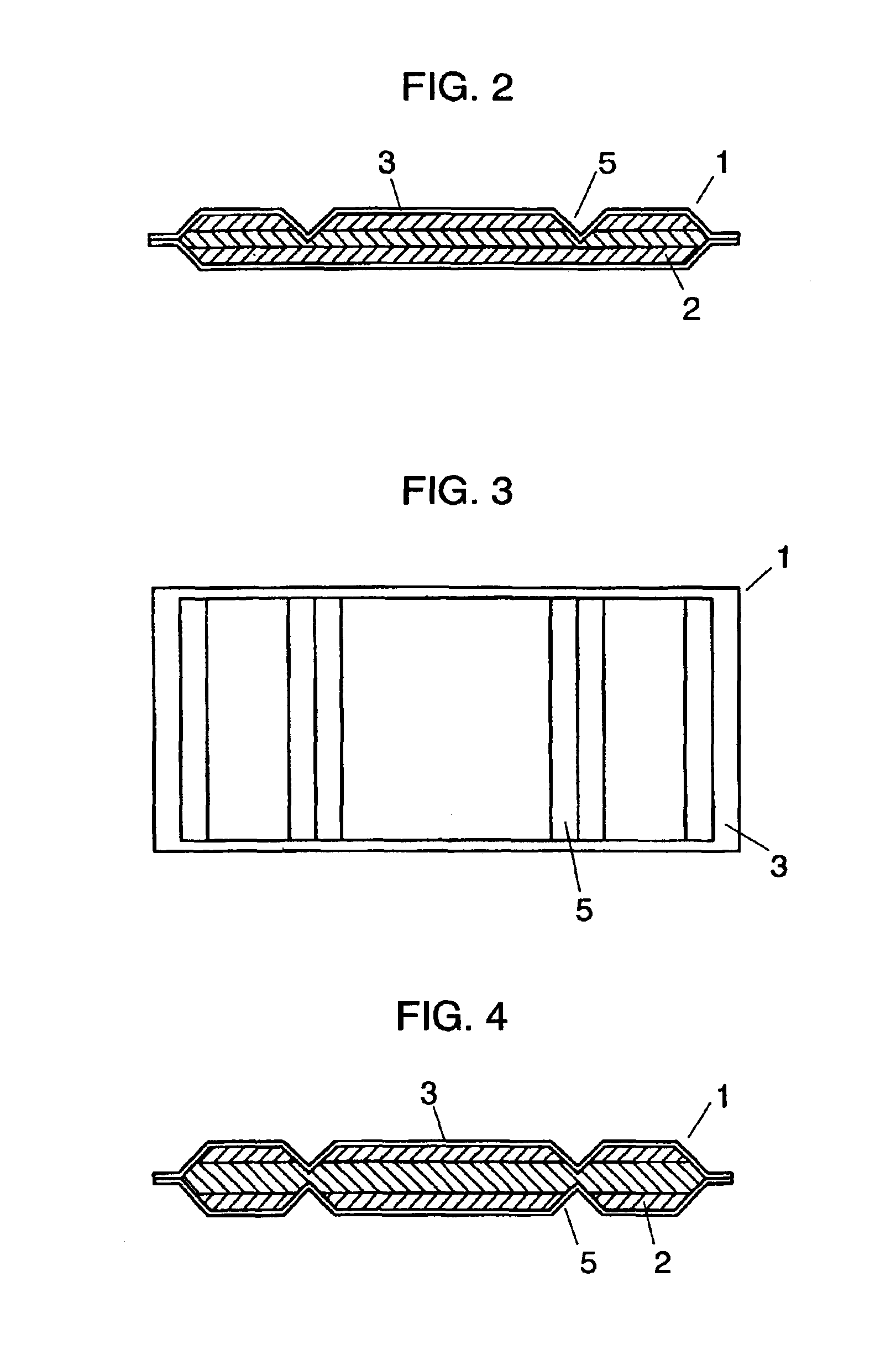
[0092]FIG. 4 is a schematic sectional view of a vacuum heat insulator of the present exemplary embodiment.

[0093]A method of fabricating the vacuum heat insulator 1, its constituent materials, and formation of a groove 5 are similar to what has been described in the second exemplary embodiment.

[0094]According to a structure shown in FIG. 4, the vacuum heat insulator is made to be easily bendable, since grooves associated with core of a small thickness can be formed in the vacuum heat insulator without causing damages to a film serving as an enveloping member with gas barrier property, even when the vacuum heat insulator has a large thickness.

[0095]In other words, when the grooves are formed in corresponding positions on front and back faces of the vacuum heat insulator, the bending process along the grooves is made easier, while also reducing substantially the damages to the enveloping member during the bending process. Even after it was subjected to a plurality of bending operations...


PUM

PropertyMeasurementUnit
Lengthaaaaaaaaaa
Lengthaaaaaaaaaa
Lengthaaaaaaaaaa

Abstract

Vacuum heat insulator comprising a laminated core made of a plurality of sheets of inorganic fibers having 10 μm or smaller in diameter and a certain composition including SiO2 as a main component, Al2O3, CaO, and MgO, a gas barrier enveloping member, and an absorbent. The vacuum heat insulator is characterized by having at least one groove formed therein after fabrication of the vacuum heat insulator. Further, the vacuum heat insulator is characterized by using inorganic fiber core of which a peak of distribution in fiber diameter lies between 1 μm or smaller and 0.1 μm or larger, and not containing binding material for binding the fiber material. Electronic apparatuses use the vacuum heat insulator. With use of the vacuum heat insulator, electronic and electric apparatuses superior in energy saving and not to present uncomfortable feeling to the user can be provided.

Description

TECHNICAL FIELD[0001]The present invention relates to vacuum heat insulator useful as insulating material for electric home appliances, and apparatuses employing this vacuum heat insulator such as refrigerators, hot / cold reserving boxes, water heaters, vending machines, notebook-type computers, and the like.BACKGROUND OF THE INVENTION[0002]It has become an important work in recent years to make positive actions against protection of the earth environment. Since energy saving is an urgent demand for electric home appliances, it is an important task to improve efficiency of heat insulation for the products such as refrigerators and hot / cold preserving boxes. In addition, high performance of insulating material also becomes inevitable for a variety of other home appliances and electronic apparatuses in order to facilitate energy saving.[0003]Furthermore, as a recently occurring problem in notebook computers, heat generated within a computer is transferred to a surface of the device enc...

Claims


Application Information

Patent Timeline
IPC IPC(8): B65D81/38B65D81/18C03C13/00F25D23/06F16L59/06F16L59/065
CPCB65D81/18B65D81/3823B65D81/3897C03C13/00F16L59/065F25D23/062Y10T428/1362F25D2201/124F25D2201/126F25D2201/14F25D2400/04Y10T428/231F16L59/06
Inventor TANIMOTO, YASUAKITENRA, TOMOHISANAKANISHI, MASAYUKIYUASA, AKIKO
Owner PANASONIC CORP
Why Eureka
Try Eureka