Scaffold

a technology of scaffolds and spherical plates, applied in the field of spherical plates, can solve the problems of less control of biodegradability, poor handling, and use of natural polymers, and achieve the effect of dimensional stability over the time required

Active Publication Date: 2012-12-25
SMITH & NEPHEW INC
View PDF110 Cites 61 Cited by
  • Summary
  • Abstract
  • Description
  • Claims
  • Application Information

AI Technical Summary

Benefits of technology

[0010]Surprisingly, we have identified scaffolds having an architecture that is optimal for cell adhesion, proliferation and migration whilst also demonstrating dimensional stability over the time required for these initial cellular processes.
[0011]Blood contains various specialised cell types which are classified into: erythrocytes, leukocytes and platelets. A primary function of platelets, also referred to as thrombocytes, is hematostasis. Platelets release a number of factors into the blood including ECM proteins and cytokines such as growth factors and other proinflammatory factors like serotonin, bradykinin, prostaglandins, prostacyclins, thromboxane, and histamine, thereby increasing cell proliferation and migration to the area and causing blood vessels to become dilated and porous.
[0012]Local administration of certain cell types has been shown to be more effective than the local administration of exogenous factors. Therefore in certain circumstances it may be desirable to selectively recover a particular therapeutically beneficial subset of cells from a blood sample. For example, it may be desirable to selectively isolate and recover the platelet population from a blood sample in order that an exogenous source of platelets can be immediately provided at a wound site to enhance the bodies inherent repair mechanism.

Problems solved by technology

However, there are concerns over the use of natural polymers because of the potential pathogen transmission, immune reactions, poor handling, mechanical properties and less controlled biodegradability1.
This will however have a negative effect on the migration of the cells into the scaffold, potentially leading to a restricted regeneration of replacement tissue around the periphery of the scaffold, with the core of the scaffold being substantially acellular.
An unanticipated problem associated with many of the known electrospun scaffolds is that they become dimensionally unstable when incubated in aqueous solution at body temperature.
Dimensionally unstable scaffolds will be of minimal use as their shrinkage can potentially have a significant impact on the behaviour of the scaffold and its interaction with the cellular environment.
Additionally, scaffolds implanted without cells do not demonstrate the same structural integrity as cell-seeded devices.
This results in a prolonged period until the device is truly functional, during which time it may fail.
However, the use of bioreactors is expensive, technically challenging and takes many weeks to produce the final product.
Attempts at injecting cells directly into pre-implanted scaffolds does not lead to suitable distribution throughout the scaffold resulting in a loss of function.

Method used


Image

  • Scaffold
  • Scaffold
  • Scaffold

Examples


example 1

Method of Manufacturing an Electrospun Scaffold for Use in the Cell Capturing Device

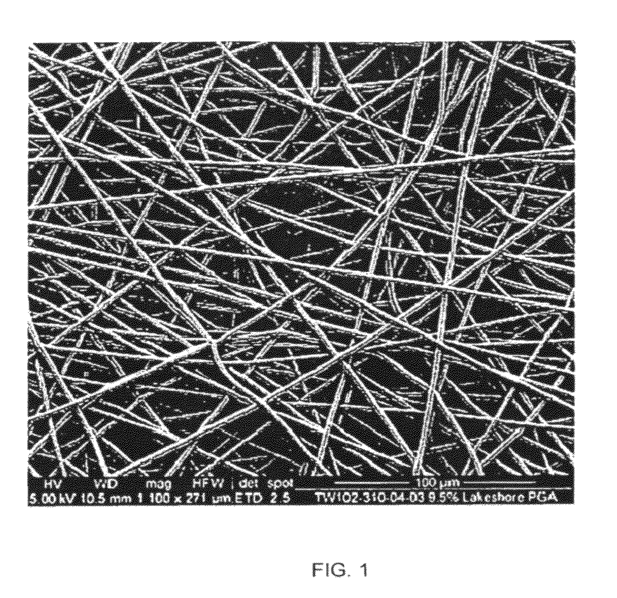
[0129]Electrospun scaffolds were produced by the process of electrospinning using polyglycolide (PGA), poly(lactide-co-glycolide) (PLGA), polyglycolide trimethyl carbonate (PGA-co-TMC), polycaprolactone (PCL), poly(D-lactide) (PDLA) and poly(L-lactide) (PLLA). The polymer solution was placed into a 10 ml syringe residing in a syringe pump, which was set to dispense the polymer at the required rate. The syringe tip was then attached to a tube (1.5 mm internal diameter) with other end attached to an 18 gauge needle that had been horizontally cut to remove its taper. The needle was clamped vertically between 10 and 20 cm above a target within a box (internal dimensions: 55 cm wide×60 high×60 deep) used to minimise air movement while electrospinning. The target consisted of a metal roller, known as the mandrel, which was attached to a motor that was rotated up to 2000 rpm to give an even coating of nano-...

example 2

Isolation of Bone Marrow Cell Suspension

[0131]Trabecular bone was removed from two femoral heads from freshly culled pigs obtained from the abattoir on the day of sampling. The femur was detached from the knee and all the muscle, cartilage, tendons and any other tissue that could contaminate the marrow sample were removed. The femoral head was dissected using a coping saw to expose the trabecular bone, which was removed with a borer under sterile conditions.

example 3

Cell Suspension Dilution and Optimum Concentration

[0132]The cells isolated from bone marrow from the femoral head were initially a solid fraction, which would not pass through the meshes, so the cells were diluted into to a fluid fraction. The bone marrow was diluted down in either phosphate buffer saline (PBS), plasma or fresh porcine blood to a concentration of 1×10⁷ white blood cells (WBC) / ml. A 100 μl aliquot of the cell suspension was removed for counting on the Coulter counter (Beckman Coulter Ac.T 5 diff. Counter). The Beckman Coulter counter counted the number of categories of both white and red blood cells contained within the sample based on both size and granularity, enabling measurements to be taken of the initial and final cell concentrations of the various cells, thus allowing the percentage of mononuclear cells captured on the scaffold to be calculated.


PUM

PropertyMeasurementUnit
diameteraaaaaaaaaa
diameteraaaaaaaaaa
diameteraaaaaaaaaa

Abstract

The present invention relates to scaffolds which can be used as medical devices for guided tissue regeneration and repair, in particular the invention is directed to a scaffold comprising fibers having a mean fiber diameter of between from about 1.2 to 4.0 microns, wherein the fibers comprise a glycolide. The invention further relates to the use of the scaffolds for the selective capture of cell populations for a cell source material.

Description

CROSS-REFERENCE TO RELATED APPLICATIONS[0001]This Application is a U.S. National Phase of International Application No. PCT / GB2007 / 001713filed May 10, 2007, designating the United States and published on Nov. 22, 2007, as WO 2007 / 132186, which claims the priority of Great Britain Provisional Patent Application No. 0609455.1, filed May 12, 2006, and Great Britain Provisional Patent Application No. 0702846.7, filed Feb. 14, 2007, the entire contents of all of which are hereby incorporated by reference.BACKGROUND OF THE INVENTION[0002]1. Field of the Invention[0003]The invention relates to scaffolds which can be used as medical devices for guided tissue regeneration and repair and for the selective capture of cell populations from a cell source material.[0004]2. Description of the Related Art[0005]Scaffold technologies are known for use in dermal regeneration in chronic and acute wounds. A number of these technologies exploit the biological properties of relatively pure natural polymer...

Claims


Application Information

Patent Timeline
Patent Type & Authority Patents(United States)
IPC IPC(8): A61K31/585A61K31/19C08G63/08A61L15/00
CPCC12N5/0068A61F13/00068C12N2533/40A61P17/02
Inventor FRY, NICHOLASDAGGER, ANTHONYMORSLEY, DAVIDLECOMTE, HELENETRAYHERN, ROYHOWARD, MARKFREESTONE, SARAHTHOMSON, BRIANSMITH, MARKCRALLAN, REBECCA
Owner SMITH & NEPHEW INC
Why Eureka
Try Eureka