

Non-aqueous electrolyte solutions and non-aqueous electrolyte cells comprising the same
a technology of non-aqueous electrolyte and electrolyte, which is applied in the direction of non-aqueous electrolyte cells, cell components, electrochemical generators, etc., can solve the problems of incompatibility of graphite negative electrodes of li-ion batteries with pc-based electrolytes, and achieve high discharge/charge efficiency, high voltage, and high discharge capacity
- Summary
- Abstract
- Description
- Claims
- Application Information
AI Technical Summary
Benefits of technology
Problems solved by technology
Method used
Image

Examples
example 1
Stability of TTFP with Respect to Platinum (Pt) Electrode
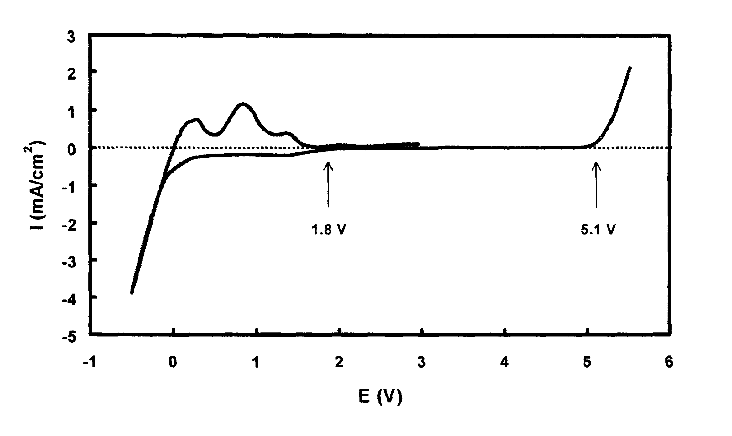
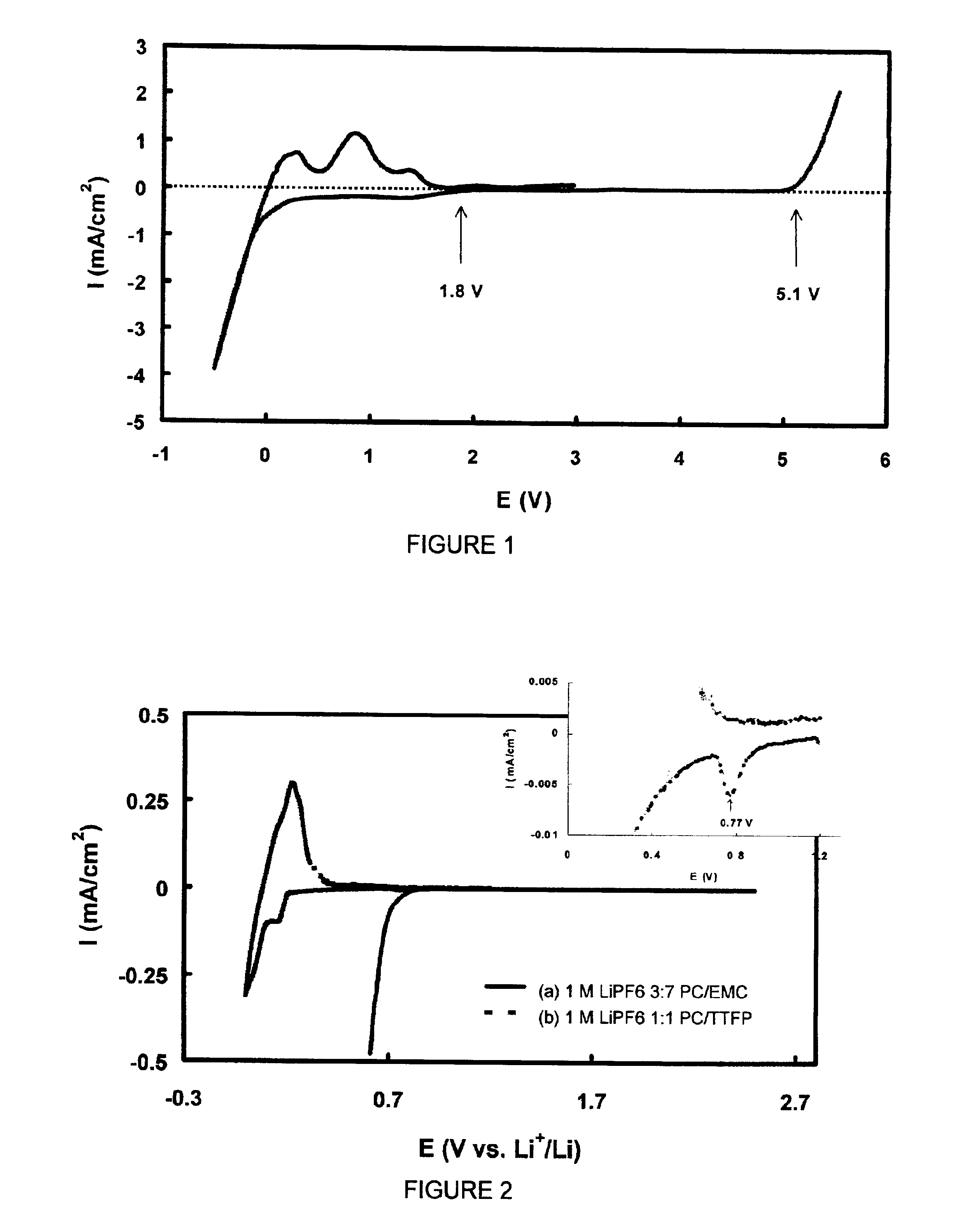
[0043]The stability of TTFP with respect to a Pt electrode was evaluated using a cyclic voltammetry technique at a potential scan rate of 5 mV / s. The working electrode was a Pt foil with an area of 8×8 mm. Both the counter and reference electrodes were lithium metal. The electrolyte used was a 1 m LiPF6 / PC-TTFP (1:1 weight ratio) solution. The voltammogram as shown in FIG. 1 indicates that with respect to Pt, the TTFP is stable up to 5.1 V in the oxidative side and starts a reductive reaction at about 1.8 V. This figure also indicates that current density of the reductive reaction is depressed at a level of 0.7 mA / cm2, until metal lithium starts to deposit at much lower potential.
example 2
Stability of 1 m LiPF6 / PC-EMC (3:7 wt Ratio) Electrolyte and 1 m LiPF6 / PC-TTFP (1:1 wt Ratio) Electrolyte with Respect to Graphite Electrode
[0044]Two identical Li / graphite cells with an electrode area of 6 cm2 were assembled. The first cell was filled with 1 m LiPF6 / PC-EMC (3:7 wt ratio) electrolyte, and the second cell was filled with 1 m LiPF6 / PC-TTFP (1:1 wt ratio) electrolyte. The stability of the electrolyte was tested using a cyclic voltammetry technique at a scanning rate of 0.01 mV / s between 2.5 V and 0 V. Cyclic voltammogram of the first cell is shown as curve (a) in FIG. 2. When the potential was scanned down to 0.8 V vs. Li+ / Li, a sharp increase in the cathodic current was found. The experiment was terminated at around 0.6 V because of too large current. A cyclic voltammogram of the second cell is shown as curve (b) in FIG. 2. The sharp increase in the cathodic current only started at below 0.2 V, and finally formed a pair of redox current peaks with an coulomb efficiency...
example 3
Discharge of Graphite Electrode in 1 m LiPF6 / PC-EMC (3:7 wt Ratio) Electrolyte and in 1 m LiPF6 / PC-TTFP (1:1 wt Ratio) Electrolyte
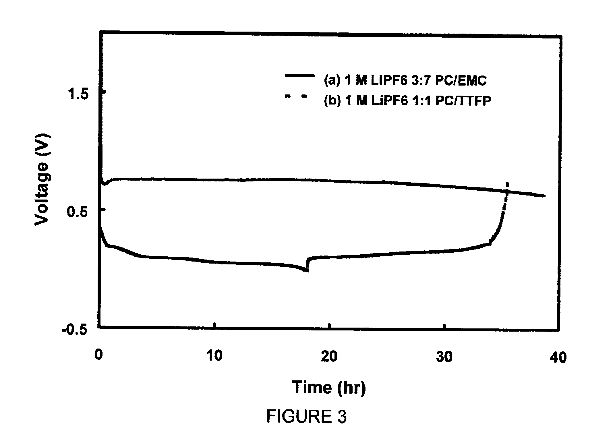
[0045]Two identical Li / graphite cells were assembled in the same manner as described in Example 2. The first cell was filled with 1 M LiPF6 / PC-EMC (3:7 wt ratio) electrolyte and the second cell was filled with 1 M LiPF6 / PC-TTFP (1:1 wt ratio) electrolyte. Both cells were discharged from open-circuit voltage (OCV) at a constant current density of 0.093 mA / cm2. The voltage of the first cell, as shown in curve (a) in FIG. 3, was shortly decreased to 0.8 V from OCV and indefinitely retained at around 0.8 V. The voltage of the second cell was able to discharge to 0.002 V and then charged back to 1.0 V at the same 0.093 mA / cm2. Curve (b) of FIG. 3 indicates a coulomb efficiency of 88% for the first intercalation and de-intercalation of Li ions into the graphite electrode. This example demonstrates that the addition of TTFP into PC could prevent the decompositio...
PUM
 Abstract
Description
Claims
Application Information