Parallel link mechanism, exposure system and method of manufacturing the same, and method of manufacturing devices

a technology of parallel link and exposure apparatus, which is applied in the direction of photomechanical apparatus, instruments, printers, etc., can solve the problems of limited use of optical materials, difficult to satisfy the rest, etc., and achieve high yield, high precision of superposition, and high integration

a technology of parallel link and exposure apparatus, which is applied in the direction of photomechanical apparatus, instruments, printers, etc., can solve the problems of limited use of optical materials, difficult to satisfy the rest, etc., and achieve high yield, high precision of superposition, and high integration

US6940582B1Inactive Publication Date: 2005-09-06NIKON CORP

Image

  • Parallel link mechanism, exposure system and method of manufacturing the same, and method of manufacturing devices
  • Parallel link mechanism, exposure system and method of manufacturing the same, and method of manufacturing devices
  • Parallel link mechanism, exposure system and method of manufacturing the same, and method of manufacturing devices

Examples


first embodiment

A First Embodiment

[0105]A first embodiment of the present invention will be described below with referring to FIGS. 1 to 8.

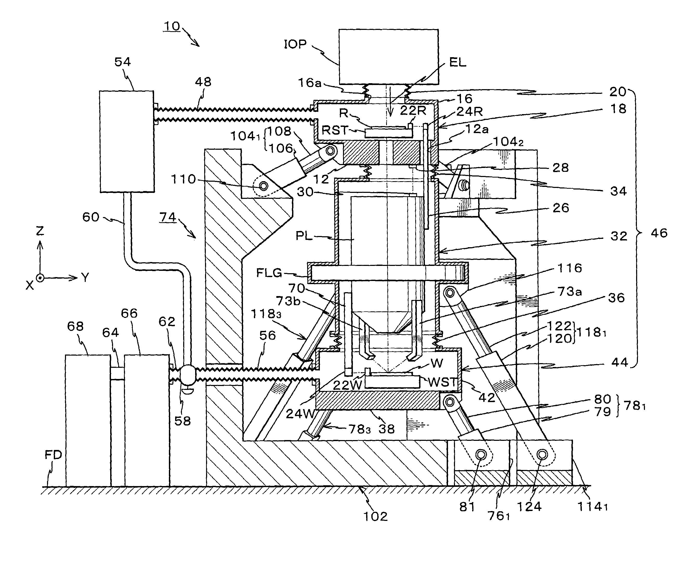
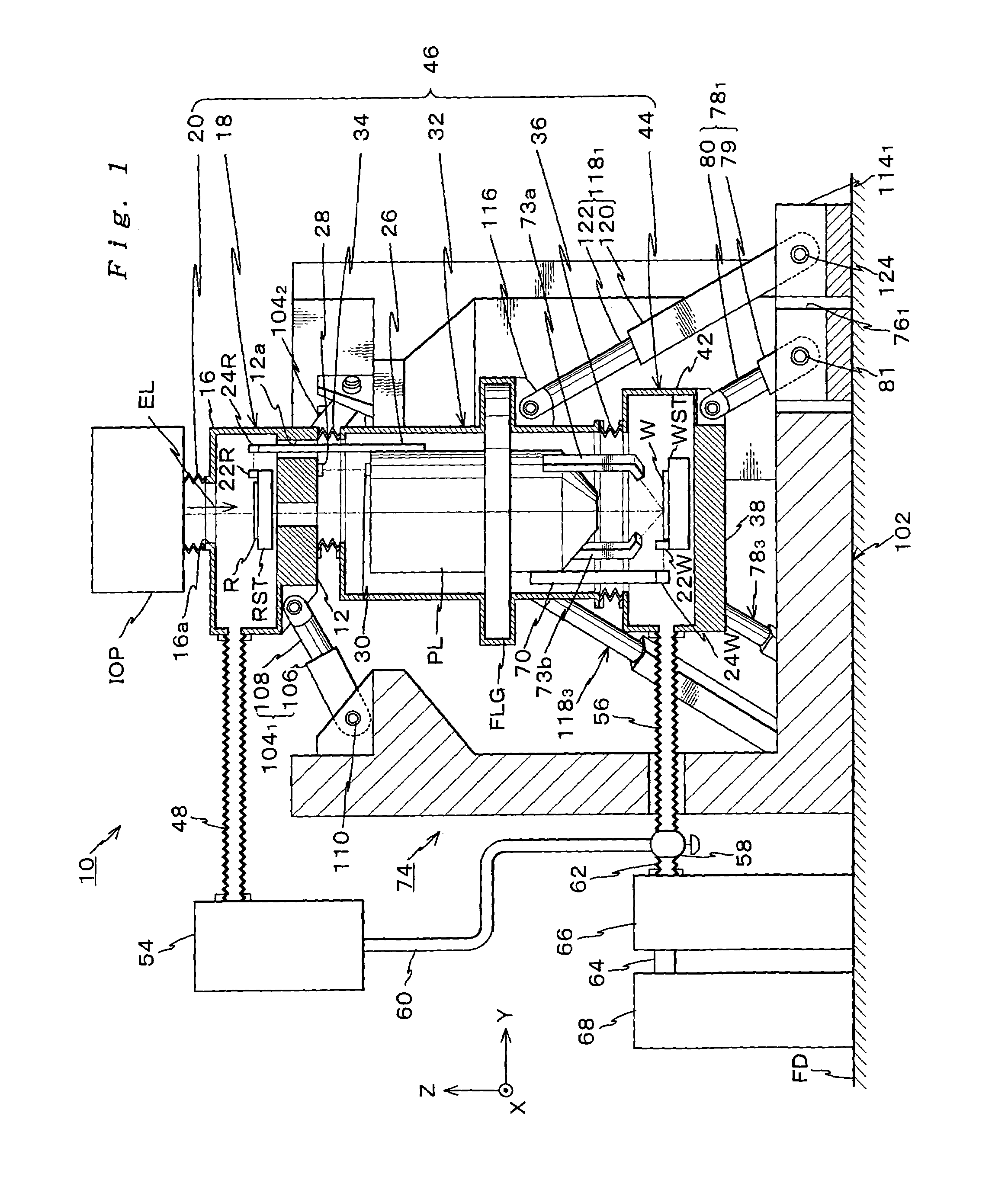
[0106]FIG. 1 shows the schematic arrangement of an exposure apparatus 10 according to an embodiment. The exposure apparatus 10 is a so-called step-and-scan type scanning exposure apparatus that while illuminating the reticle R as a mask with exposure illumination light EL that is vacuum-ultraviolet, synchronously moves reticle R and wafer W as a substrate in a scanning direction (hereafter, defined to be Y-direction that is the lateral direction in FIG. 1) and transfers a pattern on the reticle R onto a plurality of shot areas on the wafer W through a projection optical system PL. This exposure apparatus 10 is a so-called scanning stepper.

[0107]This exposure apparatus 10 includes an illumination optical system IOP that illuminates the reticle R with the exposure illumination light EL from a light source (not shown), a reticle stage RST serving as a mask stage fo...

second embodiment

A Second Embodiment

[0262]A second embodiment of the present invention will be described below with referring to FIGS. 9 to 17. Hereafter, the same or equivalent elements to those of the above first embodiment are represented by the same numbers, and for each of them, a brief or no description will be presented.

[0263]Moreover, the first and second embodiments can be employed in combination as the need arises.

[0264]FIG. 9 schematically shows an exposure apparatus 130 according to the second embodiment. This exposure apparatus is a scanning-type exposure apparatus based on a step-and-scan method, i.e. a scanning stepper, which transfers a pattern on a reticle onto a plurality of shot areas on a wafer while illuminating the reticle as a mask with an exposure illumination light EL and synchronously moving the reticle and the wafer as a substrate in a predetermined direction (hereafter, set to be Y axis direction perpendicular to the drawing of FIG. 9).

[0265]In this exposure apparatus 130...


PUM


Abstract

A reticle base level block to support a reticle stage for holding a reticle, a wafer base level block to support a wafer stage for holding a wafer, and the like are supported to be independent of other portions and be controllable in their attitudes by parallel link mechanisms each including at least three expandable rods. Therefore, the portions supported by the parallel link mechanism can be made lightweight using the advantages of the parallel link mechanism, and the attitudes of those can be precisely controlled with excellent operational-characteristics and high rigidity. In addition, transmission of vibrations and the like between the reticle base level block, the wafer base level block and other portions, e.g. an optical projection system, can be prevented. Therefore, a fine pattern formed on the reticle can be precisely transferred onto the wafer.

Description

TECHNICAL FIELD[0001]The present invention relates to a parallel link mechanism, an exposure apparatus and its making method, and a method of manufacturing a device and, more specifically, to a parallel link mechanism, a kind of mechanism, to employ at least three expandable rods and control the position / attitude of a movable object, an exposure apparatus employing the parallel link mechanism to control the attitude of at least one of a mask and a substrate and its making method, and a method of manufacturing a micro device (electronic device) by using the exposure apparatus.BACKGROUND ART[0002]In a lithography process for manufacturing a semiconductor element, liquid crystal display element, or the like, an exposure apparatus has been used. A reduction projection exposure apparatus (stepper), of a step-and-repeat method, which transfers a pattern formed on a mask or reticle (to be generically referred to as a “reticle” hereinafter) through a projection optical system onto a plurali...

Claims


Application Information

Patent Timeline
06 Sep 2005
Publication
US6940582B1
IPC
G03F7/20; H01J37/20
CPC
G03F7/70225; G03F7/707; G03F7/70716; G03F7/70725; G03F7/70833; G03F7/709; H01J37/20; H01J2237/20207
Inventors
TANAKA, KEIICHI