Multi-channel optical detection system

a detection system and multi-channel technology, applied in the field of optical detection systems, can solve the problems of long processing time, inefficiency of processes requiring precise temperature control, and affecting the quality of optical radiation measurement, so as to improve reliability, reduce maintenance requirements, and reduce processing time

Inactive Publication Date: 2005-09-06
CEPHEID INC
View PDF40 Cites 118 Cited by
  • Summary
  • Abstract
  • Description
  • Claims
  • Application Information

AI Technical Summary

Benefits of technology

[0016]The present invention overcomes the disadvantages of the prior art by providing an improved system for thermally controlling and optically interrogating reaction mixtures (e.g., biological samples mixed with chemicals or reagents). In contrast to the prior art devices described above, the system of the present invention provides excitation light to each mixture in multiple, distinct excitation wavelength ranges. This ensures that the optimal excitation wavelength range is provided for each of a plurality of analytes in the mixture having different fluorescent, phosphorescent, chemiluminescent, or electrochemiluminescent labels. In addition, the system permits the simultaneous, real-time detection of multiple analytes in the mixture without requiring any moving parts, e.g., carousels or optical filter wheels. Because it has no moving parts, the system of the present invention typically has a lower cost, lower maintenance requirements, higher reliability, and lower power consumption than the prior art devices described above.

Problems solved by technology

First, due to the large thermal mass of a metal block, the heating and cooling rates in these instruments are limited to about 1° C. / sec resulting in longer processing times. For example, in a typical PCR application, fifty cycles may require two or more hours to complete.
With these relatively slow heating and cooling rates, it has been observed that some processes requiring precise temperature control are inefficient.
For example, reactions may occur at the intermediate temperatures, creating unwanted and interfering side products, such as PCR “primer-dimers” or anomalous amplicons, which are detrimental to the analytical process.
Poor control of temperature also results in over-consumption of reagents necessary for the intended reaction.
Another disadvantage of these conventional instruments is that they typically do not permit real-time optical detection or continuous optical monitoring of the chemical reaction.
Since all of the reaction sites are sequentially excited by a single laser and since the fluorescence is detected by a single spectrometer and photomultiplier tube, simultaneous monitoring of each reaction site is not possible.
The device includes only one light source and one detector for each module, however, so that the simultaneous detection of multiple analytes is not possible.
This may cause fluorescent emissions from the sample to be weak, leading to poor optical detection sensitivity.
Second, the instrument only provides illumination light in one excitation wavelength range.
Different fluorescent dyes have different optimal excitation wavelength ranges, however, so that the instrument cannot provide excitation beams in the optimal excitation wavelength range for each of multiple fluorescent dyes in the reaction fluid.
Third, the use of dichroic filters may significantly decrease the optical sensitivity of the instrument.
For these reasons, the instrument may exhibit poor sensitivity in detecting fluorescently labeled analytes in the samples.
Although this system permits the detection of multiple fluorescent dyes in a sample volume, it has several disadvantages in its use of a moving mirror and a rotating filter wheel.
These moving parts typically result in a high cost of the optical system, high maintenance requirements, low reliability, high power consumption, and potential vibratory interference with the optical measurements.
Such tight control of temperature inhibits side reactions, such as the formation of unwanted bubbles or the degradation of components at certain temperatures, that would otherwise interfere with optical detection and analysis.

Method used


Image

  • Multi-channel optical detection system
  • Multi-channel optical detection system
  • Multi-channel optical detection system

Examples


Embodiment Construction

[0055]The present invention provides a system for thermally controlling and optically interrogating a reaction mixture, e.g., a fluid sample mixed with chemicals or reagents. As used herein, the term “fluid sample” includes both gases and liquids, preferably the latter. The sample may be an aqueous solution containing particles, cells, microorganisms, ions, or small and large molecules, such as proteins and nucleic acids, etc. In a particular use, the sample may be a bodily fluid, e.g., blood or urine, or a suspension, such as pulverized food.

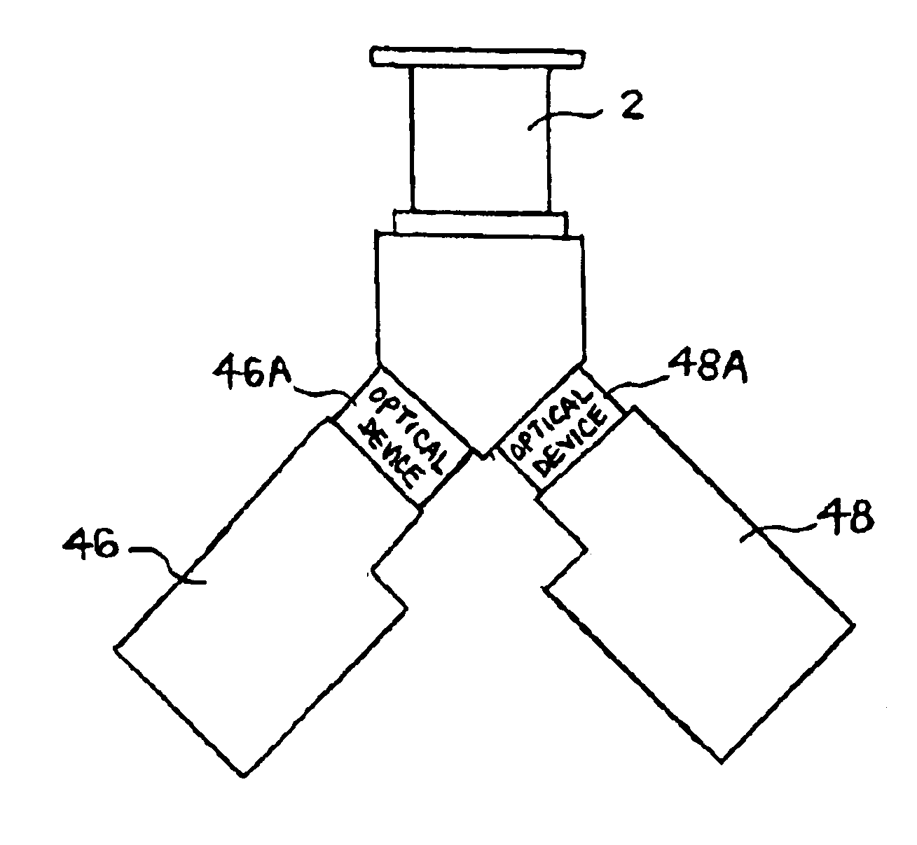
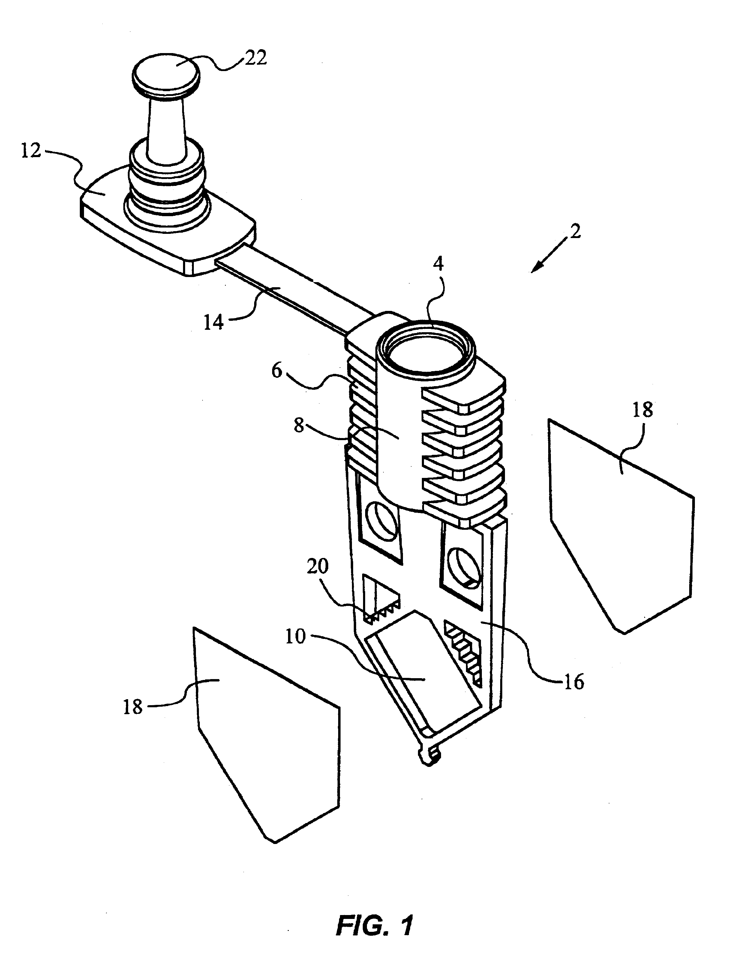
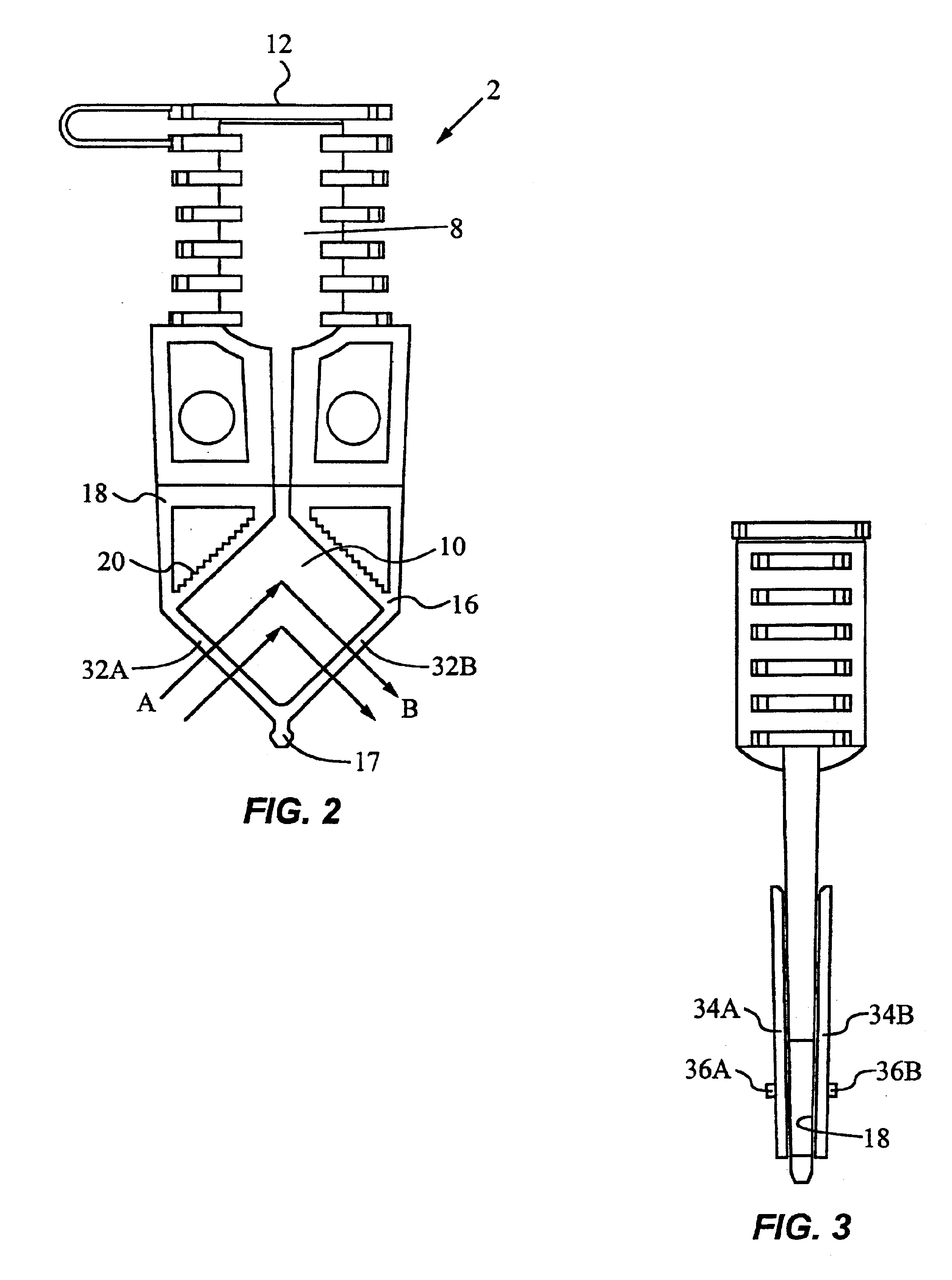
[0056]In a preferred embodiment, the system includes reaction vessels for holding the mixtures and heat-exchanging modules for receiving the vessels. Each heat-exchanging module includes a pair of opposing thermal plates between which one of the vessels is inserted for thermal processing, a fan positioned adjacent the plates for cooling the mixture, one or more temperature sensors for measuring the temperature of the plates, and a pair of optic...


PUM


Abstract

An apparatus for thermally controlling and optically interrogating a reaction mixture includes a vessel [2] having a chamber [10] for holding the mixture. The apparatus also includes a heat-exchanging module [37] having a pair of opposing thermal plates [34A, 34B] for receiving the vessel [2] between them and for heating / and or cooling the mixture contained in the vessel. The module [37] also includes optical excitation and detection assemblies [46,48] positioned to optically interrogate the mixture. The excitation assembly [46] includes multiple light sources [100] and a set of filters for sequentially illuminating labeled analytes in the mixture with excitation beams in multiple excitation wavelength ranges. The detection assembly [48] includes multiple detectors [102] and a second set of filters for detecting light emitted from the chamber [10] in multiple emission wavelength ranges. The optics assemblies [46,48] thus provide a multi-channel system for detecting a plurality of different target analytes in the mixture.

Description

RELATED APPLICATION INFORMATION[0001]This application is a continuation of U.S. application Ser. No. 09 / 314,605 filed May 19, 1999, now U.S. Pat. No. 6,369,893, and a continuation-in part of U.S. application Ser. No. 09 / 081,260 filed May 19, 1998, now abandoned, and a continuation-in-part of U.S. application Ser. No. 09 / 194,374 filed on Jul. 25, 2000 filed as a national stage entry (371) of International application No. PCT / US98 / 03962 Mar. 2, 1998, now U.S. Pat. No. 6,565,815. All of these applications are incorporated by reference herein.[0002]This invention was made with Government support under contract DAAM01-96-C-0061 awarded by the U.S. Army. The Government has certain rights in the invention.TECHNICAL FIELD OF THE INVENTION[0003]The present invention relates generally to optical detection systems, and in particular to a multi-channel detection system for the real-time detection of a plurality of different analytes in a fluid sample.BACKGROUND OF THE INVENTION[0004]There are m...

Claims


Application Information

Patent Timeline
Patent Type & Authority Patents(United States)
IPC IPC(8): G01N21/03B01J19/00B01L3/00B01L3/14B01L7/00F28F3/12F28F21/04G01N35/00
CPCB01J19/0093B01L3/508B01L7/52F28F3/12F28F21/04G01N21/0303G01N21/0332B01L3/5082B01L2300/042B01L2300/0809B01L2300/0858B01L2300/168B01L2300/1805F28D2021/0077F28F2280/10G01N2035/00326
Inventor CHRISTEL, LEE A.NORTHRUP, M. ALLENPETERSEN, KURT E.MCMILLAN, WILLIAM A.KOVACS, GREGORY T. A.YOUNG, STEVEN J.CHANG, RONALDDORITY, DOUGLAS B.HEBERT, RAYMOND T.KINTZ, GREGORY J.
Owner CEPHEID INC
Why Eureka
Try Eureka