
Method for finding contours in an image of an object

Inactive Publication Date: 2005-09-06
COGNEX TECH & INVESTMENT
View PDF28 Cites 64 Cited by
  • Summary
  • Abstract
  • Description
  • Claims
  • Application Information

AI Technical Summary

Benefits of technology

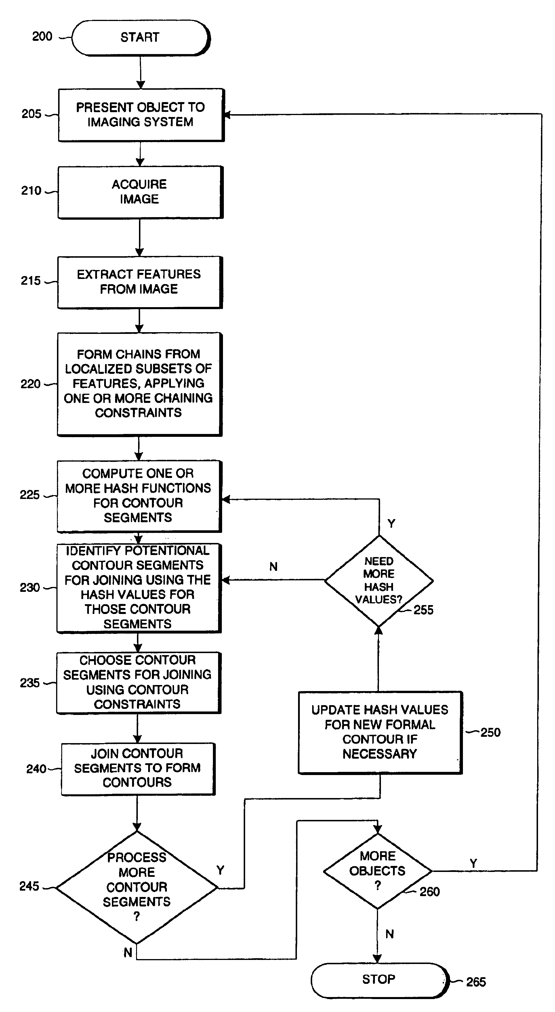
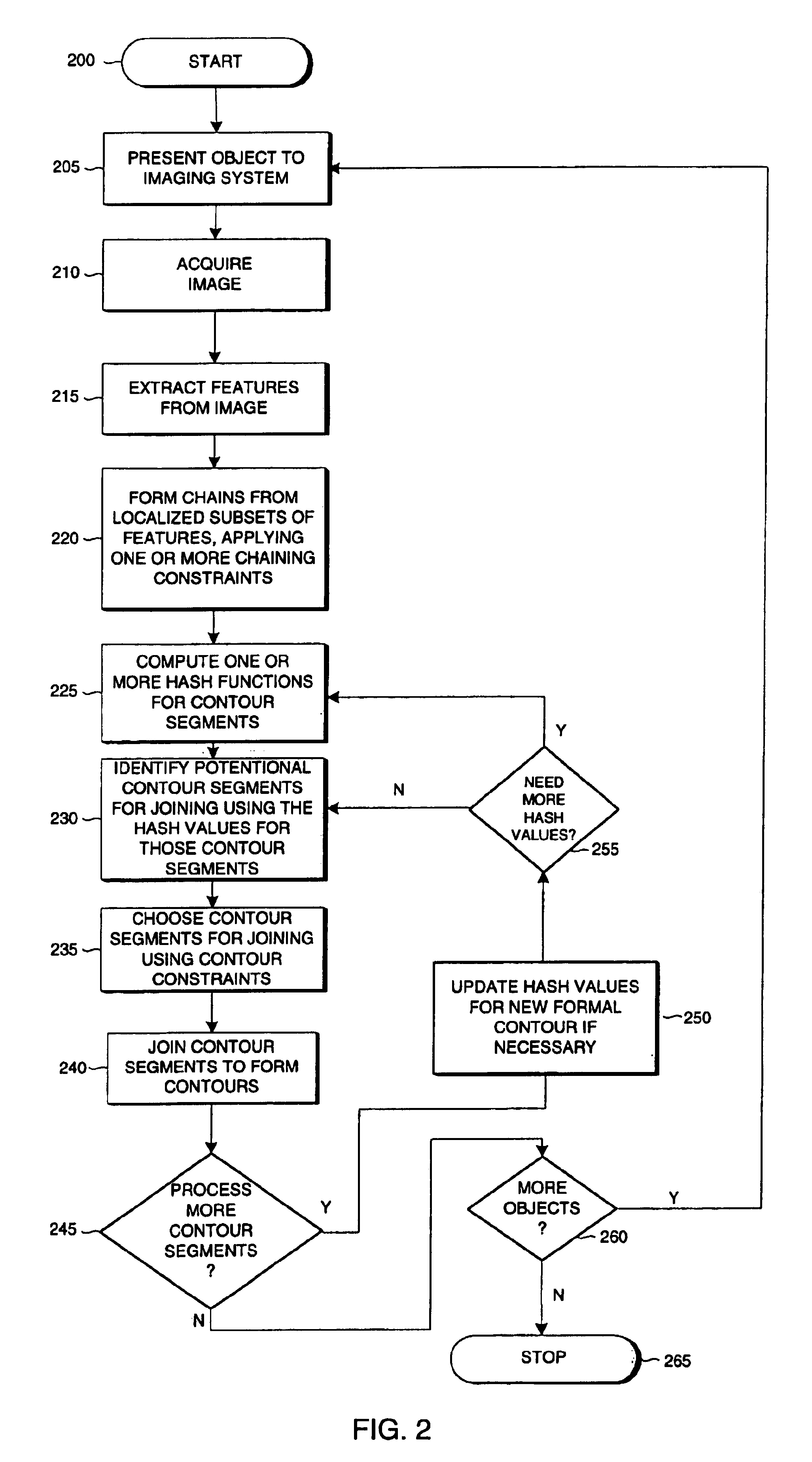
[0031]In accordance with the principles of the present invention, features are extracted from an image, those features are chained using local connectivity analysis with chaining constraints to form contour segments, contour segments are successively selected as candidates for joining together to form contours using hash functions to greatly reduce the number of candidates that need to be considered, and contour constraints are used to choose among the candidates. An example of a contour constraint useful for finding straight lines with relatively small internal gaps would be that the endpoints of the two contour segments would need to be close and the overall RMS error of a line fit through the points of both segments would need to be small.
[0034]This process can be iterated, optionally varying the constraints on the metrics, to allow efficiently building up of higher order features. For example, once an initial pass is made which considers only very close contour segments, a second pass can then be made where a greater separation is allowed for groups of segments of a certain length, perhaps also placing tighter constraints on the angles.
[0035]This invention overcomes limitations of the prior art by providing methods for effectively analyzing surface inspection images to identify low contrast contours and discontinuous contours of arbitrary shape.
[0036]The present invention makes contour identification in machine vision images more efficient and robust. Curves that cannot be found by other techniques can be found by methods according to the present invention. Disadvantages of the Hough transform including false correlation of sparse contour segments are overcome according to the present invention. Quantization error effects that plague known Hough transform methods are also avoided by the method of the present invention. The present invention further overcomes the disadvantages of known chaining methods by bridging local gaps in low contrast defects. The present invention further overcomes the disadvantages of known global contour finding methods by using hash functions to reduce the computational complexity.

Problems solved by technology

Due to the vast number of possible surface qualities and textures, machine vision applications that are useful for inspecting certain surface types may not be well suited for inspecting certain different surface types.
This process can cause defects, which if undetected can block the proper transmission of light through a fiber.
Although manual inspection methods are expensive, the alternative, i.e., machine vision inspection of optical fiber end surfaces, has proven difficult to implement.
Optical fiber end surface inspection has presented many obstacles to the application of automated inspection techniques using machine vision systems.
While standard machine vision methods are adequate for many industrial machine vision applications, highly specialized operations, like inspecting polished fiber ends, often require specialized vision methods.
The lines often have very low contrast and are speckled with noise and texture artifacts and therefore do not always appear continuous to common edge detection techniques that use local metrics or small kernel sizes.
Such contours that appear discontinuous in an image are particularly difficult for machine vision systems to identify.
This is not always easy to do given that there may be many confusing features in the image.
Another shortcoming of binary techniques is that they only provide whole pixel accuracy.
Also, scratches can have low contrast thus making it very difficult to find a usable threshold.
One disadvantage of template matching methods is that they require a training step wherein a model image or template of objects to be located is generated and stored.
For the inspection of fiber end surfaces, it is very difficult to generate models of defects such as scratches due to their variability.
This type of exhaustive technique is impractical since it would not run in a reasonable amount of time.
While PatMax has some flexibility in performing a rotation and scale invariant search, it is not optimal for finding scratches on fiber ends.
Geometric pattern matching techniques will have difficulty localizing line models along lines in an image.
Scratches may be of any length and finding lines of varying lengths with a single line model of a fixed length that can be scaled has problems.
The many good matches can make the tool take a long time to executed and when the line model is allowed to change scale, the match calculation can become numerically unstable.
PatMax is also susceptible to the problems with lower-level edge detectors as described next.
Also, both template matching and geometric pattern matching techniques assume that the object to be found will have a consistent appearance, and this is usually not the case for scratches in a fiber end face.
Scratches can be particularly difficult to detect because they usually have low contrast with respect to a fiber end surface.
These types of lighting and viewing angle changes can enhance the quality of the scratch contrast but still will not be enough to make simple vision techniques work.
Projections are also very susceptible to confusion by bright spots.
Also, the small-scale irregularities of the scratches will generate many false edges and miss many valid edges such that the subsequent processing steps, such as chaining, have too many features to consider, thus making such processing run slowly and produce erroneous results.
Often the problem of detecting and tracing scratches becomes a problem of grouping features such as edge features to form higher-level contours.
The line Hough has additional limitations including the generation of large numbers of candidates that must each be separately verified.
Arbitrary curves or contours, such as some fiber end scratches, however, cannot be found by any implementation of the Hough transform.
Furthermore, the quantization of Hough space into accumulator cells can introduce significant error in the reported location of candidate lines or curves.
Hough transforms also typically rely on lower level edge detection such as Sobel or Robert transforms and therefore suffer all of the limitations of those lower level operations.
Such small gaps occur quite frequently in images and are especially problematic in low contrast defects such as scratches in optical fiber end surfaces.
The method according to the Dar patent disadvantageously requires extensive pre-processing to isolate regions of suspected scratches in which to apply the Hough transform.
More significantly, the method according to the Dar patent suffers the same disadvantages of the general Hough transform in that it connects widely separated pixels that may not be part of a common contour.
The method disclosed by the Palmquist patent disadvantageously requires the acquisition of an optimal focus image and auxillary images behind and in front of the optimal focal positions.
In addition, fiber scratches that are irregular, low in contrast, or formed by a series of dots that are not necessarily connected, do not form continuous connected edges and will not be detected by this method.
In fact, edge detectors may not detect a string of dots at all.

Method used


Image

  • Method for finding contours in an image of an object
  • Method for finding contours in an image of an object
  • Method for finding contours in an image of an object

Examples


Embodiment Construction

[0042]The method according to the present invention locates contours in an image and is particularly useful in detecting defects such as scratches in optical fiber end surfaces. The method provides enhanced detection of such scratches, which typically appear as faint sets of locally disconnected features having low contrast in machine vision images.

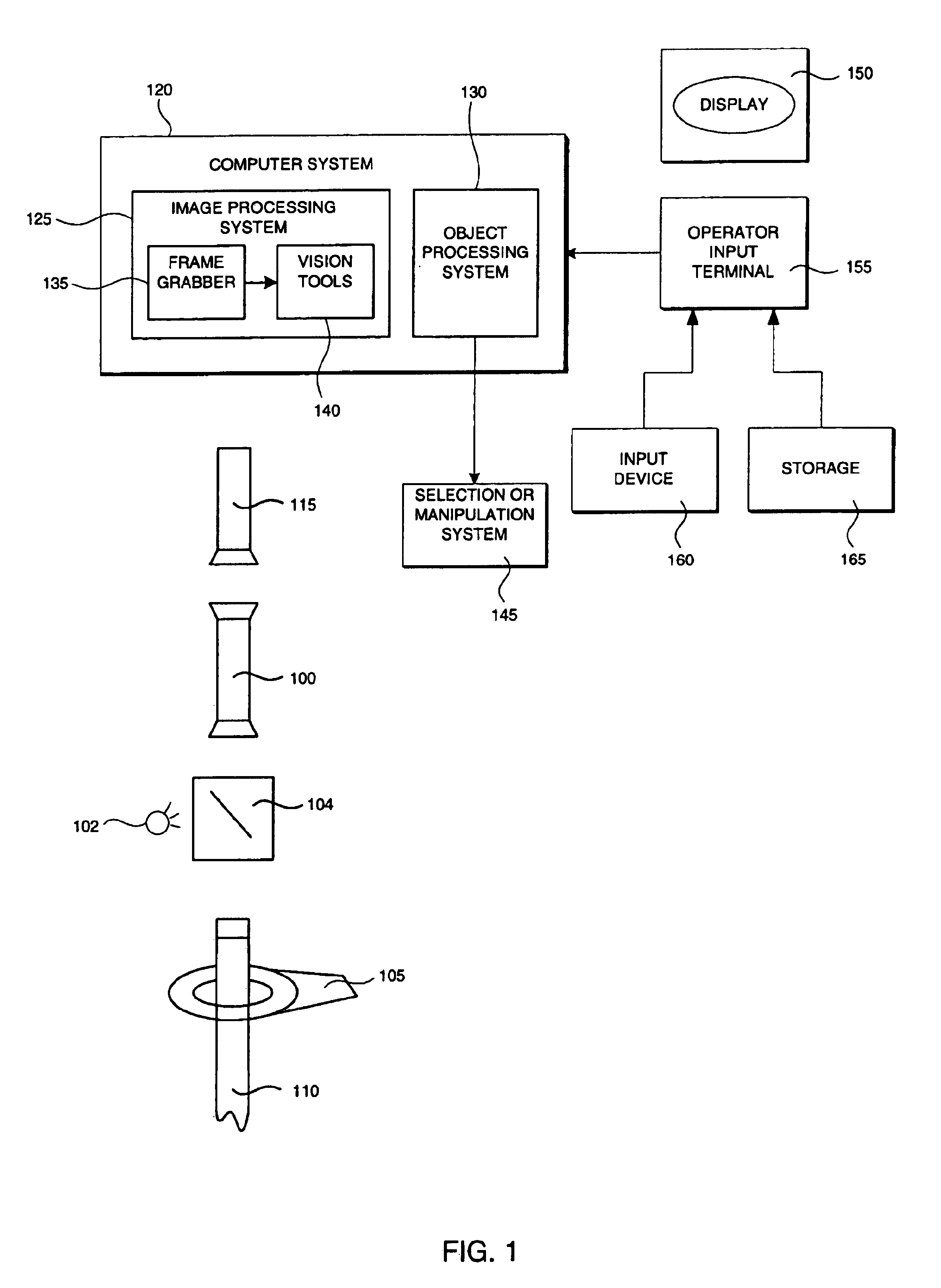
[0043]FIG. 1 illustrates in schematic form an example of a machine vision system that can utilize the process of the present invention. The example system demonstrates the inspection of the end-face of an optical fiber, but this example is merely illustrative and not restrictive. In the example system, a fiber microscope 100 examines an optical fiber 110 held in a mounting device 105. The fiber may also be presented to the system by other well-known mechanisms. When a fiber is in the mount, an image stream of the fiber is created by a camera system 115 in a conventional manner. Light is provided by a light source 102, and a half-silvered ...


PUM


Abstract

A method is provided for robustly and efficiently identifying contours in an image of an object. Features are extracted from an image, typically using a Sobel edge detector or a set of large oriented filters, and are locally chained to form contour segments of particular character, such as line segments. A spatial hash table is used to access the contour segments according to the location of their endpoints. Candidate sets for joining to grow contours are reduced by considering only segments having ends in adjacent spatial hash bins. Contour constraints are applied to appropriately choose among the candidates to form contours. The method facilitates robust and efficient scratch detection of fiber-optic end faces, or of any surface that may have smoothly curved scratches.

Description

FIELD OF THE INVENTION[0001]The invention relates to machine vision, and more particularly to machine vision inspection methods.BACKGROUND OF THE INVENTION[0002]Various manufacturing processes and other industrial processes require inspection of manufactured and processed parts to identify and / or classify defects.[0003]Automated inspection methods using machine vision techniques are commonly used to perform such inspections. Due to the vast number of possible surface qualities and textures, machine vision applications that are useful for inspecting certain surface types may not be well suited for inspecting certain different surface types. Variations in image feature contrast and reflectivity, for example, can hide critical defects in a machine vision image.[0004]Optical fiber manufacturing operations, for example, use various machine vision inspection techniques for quality assurance or in-process inspections of fiber ends. In fiber-optic cable production, once a fiber has been cle...

Claims


Application Information

Patent Timeline
IPC IPC(8): G06K9/48G06T5/00G06V10/46
CPCG06K9/4638G06K9/48G06T5/005G06T7/0004G06T7/0083G06K2009/488G06T2207/10056G06T2207/20021G06T2207/20136G06T2207/30108G06T7/12G06T7/181G06V10/457G06V10/478G06V10/46G06T5/77
Inventor WAGMAN, ADAMBACHELDER, IVAN
Owner COGNEX TECH & INVESTMENT
Learn More