
Process and gas generator for generating fuel gas

a gas generator and fuel gas technology, applied in the details of gasification process, special form destructive distillation, combustion process, etc., can solve the problems of faulty reactions, constant pressure gradient within the particulate solids bed, and inability to homogeneous solids density, etc., to achieve high fuel gas quality, reduce the cross-section of the particulate solids bed, and optimise the effect of gas quality

Inactive Publication Date: 2005-09-13
FORETOP CORP
View PDF11 Cites 21 Cited by
  • Summary
  • Abstract
  • Description
  • Claims
  • Application Information

AI Technical Summary

Benefits of technology

[0019]The generic type of the apparatus for performing such a process may be defined as a gas generator for generating a fuel gas, including a solids feeder, discharging into a dry distillation zone, wherein solids introduced by the solids feeder are heated, dried if necessary, and subjected to dry distillation thereby to release dry distillation volatiles downstream of the dry distillation zone into a gasification zone supplied with and containing a bed of gasifiable carbonaceous solids, supported on a fire grate device restricting the rate of downward movement of the solids of the bed under gravity, in co-current with dry distillation volatiles released from the dry distillation zone flowing through the bed of gasifiable carbonaceous solids, a supply of oxygen-bearing gas in the dry distillation zone supporting partial combustion for heating the dry distillation zone and a supply of gasification medium maintaining gasification conditions in the gasification zone, at least the lower region of the bed of gasifiable carbonaceous solids being maintained in an embers bed condition through which the dry distillation volatiles and volatilised products of gasification pass in order to be subjected to thermal cracking.
[0041]In order to facilitate the controlled discharge of the solids residues, the baffle formation is preferably composed of a plurality of solids guides which, viewed in the direction of discharge of the solids residues, follow each other successively. For the free throughput of the fuel gas this design provides for at least one through-flow passage in the region of the last one of these solids guide means. Between the solids guide means throughput advancing formations for the solids residues are mounted, which by turning over the solids in the discharge region and, where necessary, also by breaking up of agglomerations of solids particles accelerate the discharge. For moving the discharge element the discharge element is fitted to a rotatable drive shaft.

Problems solved by technology

It is a problem in the process of the afore described type that inside the particulate solid bed, where lumps of varying sizes occur of the organic material to be processed, no homogeneous solids density can be attained as a result of which the reduced pressure in the combustion chamber below the discharge element for the withdrawal of the gases will not result in a constantly maintained pressure gradient within the particulate solids bed.
In such regions within the particulate solids bed, in which material bridges and cavities are formed, faulty reactions and undesired flame breakthrough may occur, even in a direction opposite to the set up co-current direction.
Likewise, an inadequate conversion of the dry distillation volatiles may occur in the embers bed whereby the quality of the fuel gases generated is compromised by dry distillation volatiles inadequately cracked in the embers bed being drawn off prematurely.
Frequently the setting up of optimal parameters for the gasification process and for the conversion of dry distillation volatiles in the embers bed results in undesirable conditions in the particulate solids bed of the dry distillation zone and vice versa, such that the control of the gas processor is unstable.
The gases thereby formed are withdrawn from the rotary drum in the conveyance direction of the material in co-current It is a disadvantage that the thermal conditions for the formation of dry distillation volatiles are not adequately adaptable dynamically to the conversion in the gasification shaft reactor.

Method used


Image

  • Process and gas generator for generating fuel gas
  • Process and gas generator for generating fuel gas
  • Process and gas generator for generating fuel gas

Examples


Embodiment Construction

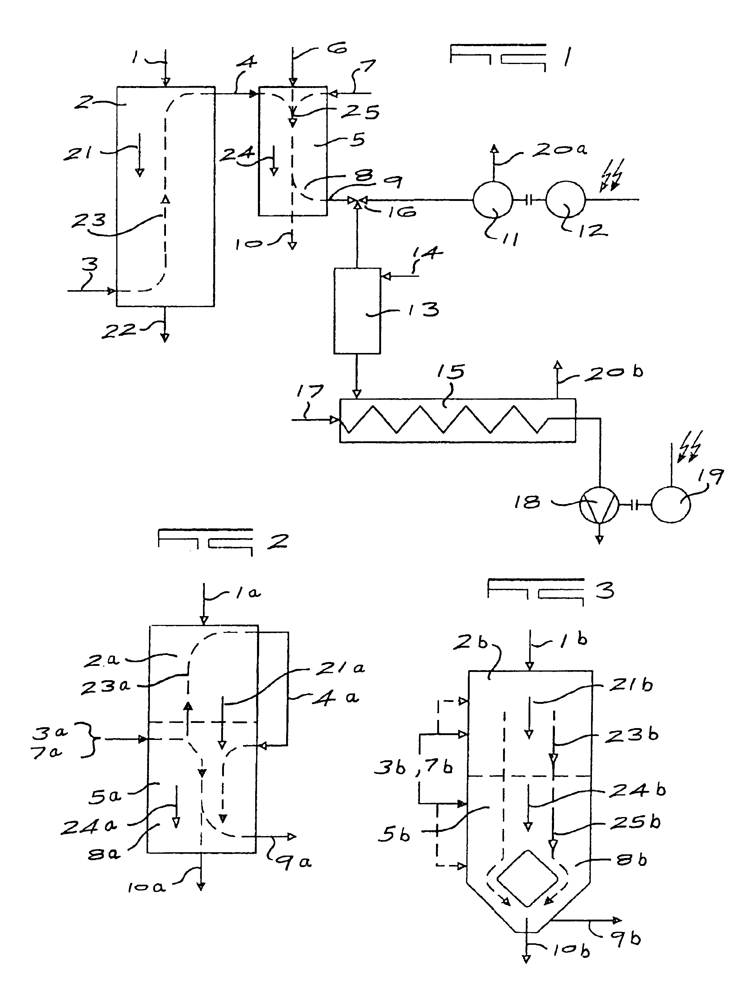
[0062]In FIG. 1 the process according to the invention is illustrated by way of a flow sheet. The solids to be gasified having organic material contents, in the working example dry-distillable biomass such as, e.g., waste wood, straw bales or even bio-garbage which is difficult to rot or plastics containing metal such as wastes from metal reinforced insulating materials or old tyres are introduced by way of a solids feed 1 into a dry distillation reactor 2 and are there heated, dried thereby and subjected to dry distillation. The solids are heated in the dry distillation reactor by partial combustion of the organic material contents with the addition of gasification medium which, in relation to the oxidisable solids content of the introduced solids, is added in substoichiometrical amount The gasification medium flows by way of a gasification means supply 3 into the dry distillation reactor 2.

[0063]The dry distillation volatiles formed in the dry distillation reactor 2 by heating of ...


PUM


Abstract

A process and gas generator is disclosed for generating by dry distillation of solids and gasification of solids, a fuel gas substantially free of condensable dry distillation volatiles which would interfere with the intended use of the gas, e.g. for powering an internal combustion engine.To achieve this, solids beds in distinct dry distillation and gasification zones are maintained under conditions favouring thermal cracking of condensable (tar) volatiles in the hot regions of both zones. For optimal control of these conditions these zones are physically separated by internals within a single reactor vessel and optionally by performing part of the dry distillation (pyrolysis) in a separate reactor vessel, in which case pyrolysis volatiles are fed in counter-current to the dry distillation bed, withdrawn from the top thereof and fed into and through the embers bed of the gasification zone. Thermal cracking of pyrolysis volatiles is prolonged and intensified by the manner in which these volatiles are conducted in intimate contact through the embers bed of the gasification zone in co-current therewith. The embers bed is guided along a progressively constricting pathway, which controls the rate of travel of and the period of residence of the solids bed in the process and generator.

Description

FIELD OF THE INVENTION[0001]The invention relates to a process for generating fuel gas by dry distillation of solids and subsequent gasification of solids. The invention also relates to a gas generator suitable for performing the process.BACKGROUND OF THE INVENTION[0002]The invention is based on the following state of the art:[0003]The invention starts from a process such as may, for example, be performed using a gas processor as described in DE 33 12 863 C2. In that process the solid matter to be processed which contains gasifiable organic material, passes under the action of gravity through a pyrolysis chamber in which initially—in the absence of air—these solids are thermally subjected to dry distillation at a temperature of about 500° C. and are subsequently gasified for fuel gas generation by the addition of gasification medium at a temperature of about 800° C. The gasification media are introduced substoichiometrically in relation to the oxidisable material content. The organi...

Claims


Application Information

Patent Timeline
IPC IPC(8): C10J3/14C10J3/02C10J3/00C10B53/00C10B49/00C10B53/02C10J3/66C10B49/06F02C3/26F02C3/28
CPCC10B49/06C10B53/02C10J3/14C10J3/66F02C3/28C10J3/74C10K3/02Y02E20/12Y02E50/14Y02T50/671C10J2300/165C10J2300/1671C10J2300/1884Y02E50/10Y02T50/60
Inventor HAHN, HANS HELMUTMALLEK, HEINZ GUSTAVBRAEKER, KIRSTENMOSCH, HEINRICH
Owner FORETOP CORP
Learn More