Passive cooling system for auxiliary power unit installation

a cooling system and auxiliary power unit technology, applied in the direction of efficient propulsion technologies, machines/engines, transportation and packaging, etc., can solve the problems of significantly reducing the operation speed of these fans, and reducing the reliability of auxiliary power units. , to achieve the effect of improving the cooling of oil and enhancing the cooling airflow

Inactive Publication Date: 2005-09-13
PRATT & WHITNEY CANADA CORP
View PDF71 Cites 82 Cited by
  • Summary
  • Abstract
  • Description
  • Claims
  • Application Information

AI Technical Summary

Benefits of technology

[0010]It is also an object of the present invention to provide a simpler cooling system for auxiliary power unit engine oil and external components which does not require moving parts and does not include a cooling fan.
[0011]It is a further object of the present invention to provide improved cooling of the oil in an auxiliary power unit by providing enhanced cooling airflow through the heat exchanger.

Problems solved by technology

The mechanical complexity and high operating speeds of these fans increases the possibility of failure.
Active fan cooling systems therefore can significantly reduce the reliability of an auxiliary power unit.
This arrangement causes the cooling air to be heated up in the compartment before it reaches the oil cooler, and therefore, oil cooling is not optimized.

Method used


Image

  • Passive cooling system for auxiliary power unit installation
  • Passive cooling system for auxiliary power unit installation
  • Passive cooling system for auxiliary power unit installation

Examples


Embodiment Construction

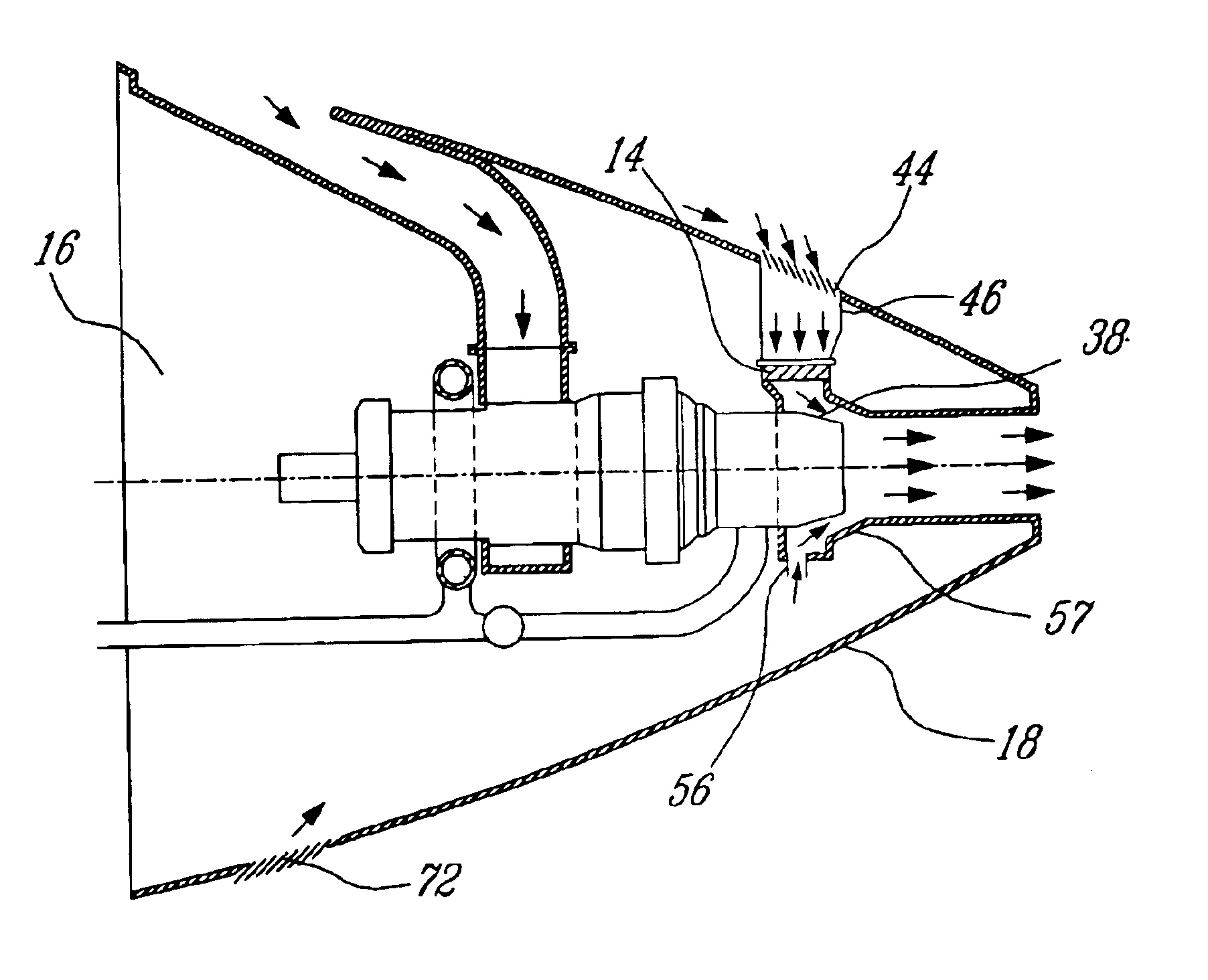
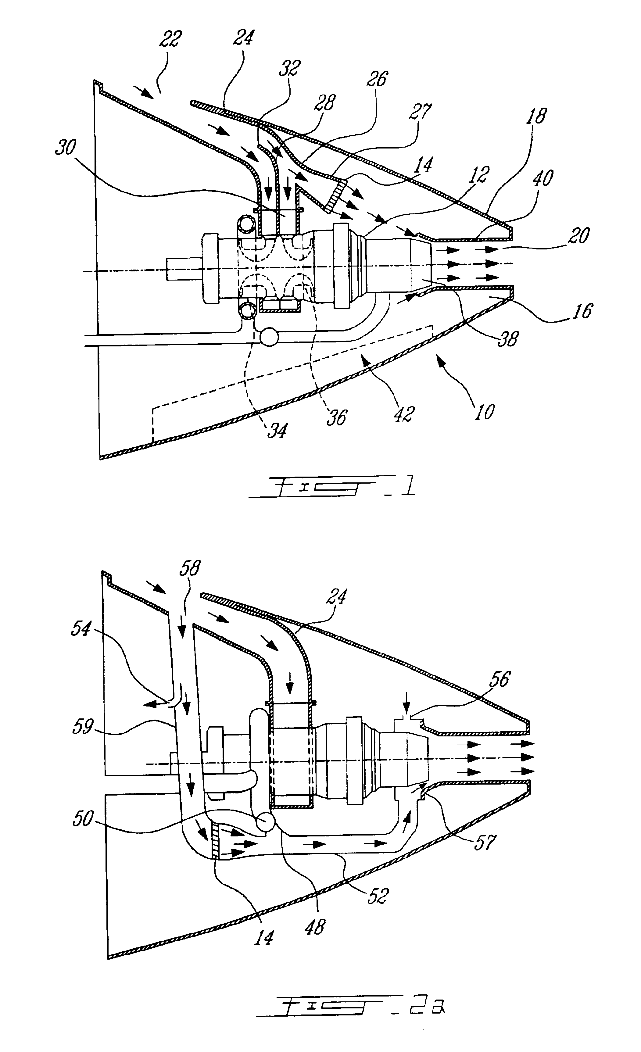
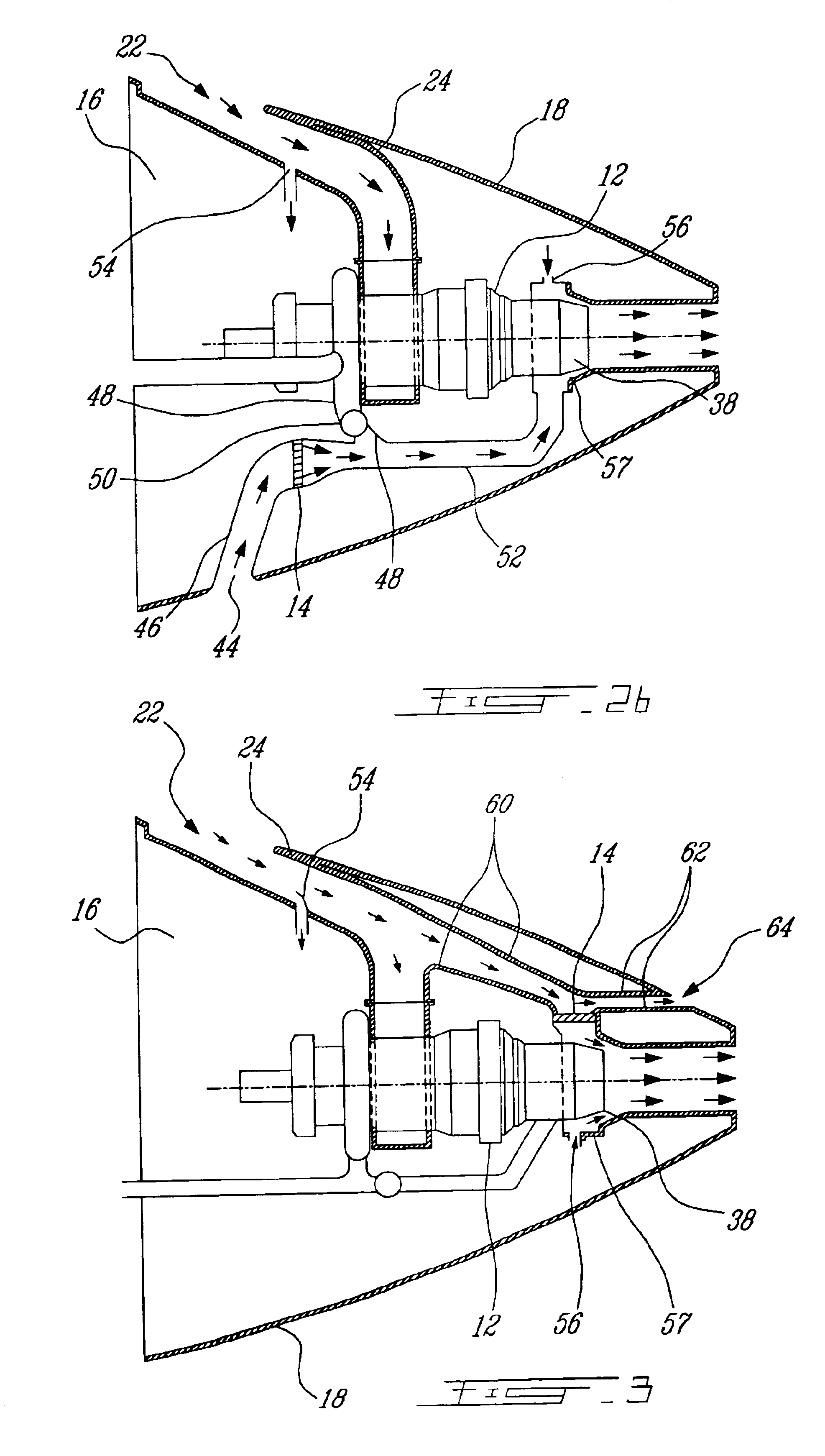
[0026]Referring to the drawings, FIG. 1 embodies an APU installation 10 comprising the elements of the present invention that will be described. The APU installation 10 is principally comprised of a gas turbine power plant 12 and an oil cooler 14, both within an auxiliary power unit nacelle 16. This nacelle is defined for the purposes of the present invention, as any dedicated enclosed compartment or enclosure, generally although not essentially located within the aircraft tailcone. The nacelle 16 shown in these embodiments as an aft compartment in the aircraft, has an exterior skin surface 18. Compartment access doors 42 allow external access to the auxiliary power unit when the aircraft is on the ground, for such purposes as engine maintenance.

[0027]In the embodiment shown in FIG. 1, the exterior surface 18 of the APU nacelle 16 comprises principally two openings, the rear exhaust opening 20 and the main air inlet opening 22. The main air inlet opening 22 in the aircraft exterior ...


PUM


Abstract

A passive cooling system for an auxiliary power unit (APU) installation on an aircraft is provided. The system is for an auxiliary power unit having at least a compressor portion of a gas turbine engine and an oil cooler contained separately within a nacelle. The system includes the auxiliary power unit housed within the nacelle of the aircraft, an engine exhaust opening defined in the aft portion of the nacelle and communicating with the gas turbine engine, at least a first air inlet duct communicating with a second opening defined in said nacelle and with said compressor portion and the oil cooler is located within a second duct communicating with an opening other than the engine exhaust opening of said nacelle and with the engine exhaust opening. Exterior cooling air and engine exhaust ejected through said engine exhaust opening entrain cooling air through said second duct to said oil cooler, and thus provide engine oil cooling. An exhaust eductor is also provided.

Description

[0001]This application is a continuation of U.S. patent application Ser. No. 10 / 020,363 filed Oct. 29, 2001, now issued as U.S. Pat. No. 6,651,929.TECHNICAL FIELD[0002]The present invention relates to cooling systems for auxiliary power units on airplanes and, more particularly, pertains to the passive cooling of the components and oil of such units and the enclosure ventilation of such units.BACKGROUND OF THE INVENTION[0003]Large aircraft often use an on-board auxiliary power unit (APU) to provide electrical power and compressed air for systems throughout the airplane. When the aircraft is grounded, the APU provides the main source of power for environmental control systems, hydraulic pumps, electrical systems and main engine starters. During flight, the APU can supply pneumatic and electric power.[0004]Auxiliary power units are generally small gas turbine engines, often mounted in the aft tail section of the aircraft. They require a certain amount of cooling air, and are lubricate...

Claims


Application Information

Patent Timeline
Patent Type & Authority Patents(United States)
IPC IPC(8): B64D33/08B64D33/00B64D33/10B64D41/00F01D25/18F01M5/00F02C7/06F02K1/04
CPCB64D33/08B64D33/10B64D41/00F02C7/14B64D2033/0213B64D2041/002Y02T50/675F05D2220/50F05D2260/20Y02T50/60
Inventor DIONNE, LUC
Owner PRATT & WHITNEY CANADA CORP
Why Eureka
Try Eureka