Disposable sub-microliter volume biosensor with enhanced sample inlet

a biosensor and sub-microliter technology, applied in the field of electrochemical sensors, can solve the problems of inconvenient procedures, vision loss, kidney failure and vascular diseases, etc., and achieve the effects of convenient sample introduction, short wait time, and wide linear measurement rang

Inactive Publication Date: 2005-09-13
NOVA BIOMEDICAL
View PDF26 Cites 182 Cited by
  • Summary
  • Abstract
  • Description
  • Claims
  • Application Information

AI Technical Summary

Benefits of technology

[0011]It is an object of the present invention to provide an improved electrochemical sensor which combines an enzyme and a mediator. It is a further object of the present invention to provide an electrochemical sensor which requires less sample volume than previously required by the prior art. It is still another object of the present invention to provide an electrochemical sensor which can measure a small volume of sample without the use of a mesh layer in the sample path. It is yet another object of the present invention to provide an electrochemical sensor which has a wide linear measurement range and a relatively short wait time for development of a steady-state response. It is another object of the present invention to provide an electrochemical sensor that has a modified inlet port to facilitate sample introduction.
[0012]The present invention achieves these and other objectives by providing an electrochemical sensor which requires a sample size of only about 0.2 microliters and does not use a mesh layer in the sample path as a means of achieving a reduced size of the sample. Further the present invention uses a reagent composition which allows readings, which correlate very closely to the analyte concentration in the fluid sample, to be taken 5 seconds after the fluid sample enters the sample channel.
[0016]The unique feature of the present invention is its ability to measure sample sizes as small as 0.10 microliters, or smaller, without using opposing working and reference electrodes and a sorbent / mesh layer therebetween to reduce the required sample volume for measurement. This is is achieved by reducing the width and length of the U-shaped cutout and by using a thinner middle layer.
[0019]The laminated body of the present invention has a top layer with a vent opening and an inlet notch. The vent opening is located such that at least a portion of the vent opening overlays the bottom of the U-shaped cutout exposing a portion of the chemical reagent of the middle insulating layer. The vent allows air within the sample fluid channel to escape as the sample fluid enters the open end of the laminated body. The inlet notch facilitates sample introduction through the inlet by creating a top inlet aperture, which is in communication with the end of the inlet of the sensor. In the event that the sample inlet port is inadvertently blocked by the source of the blood sample such as a finger, the inlet notch remains open for receiving the sample fluid.

Problems solved by technology

Because this disorder can cause dangerous anomalies in blood chemistry and is believed to be a contributor to vision loss and kidney failure, most diabetics need to test themselves periodically and adjust their glucose level accordingly, usually with insulin injections.
If the concentration of blood glucose is below the normal range, patients can suffer from unconsciousness and lowered blood pressure which may even result in death.
If the fasting blood glucose concentration is higher than the normal range, this can result in vision loss, kidney failure and vascular diseases.
However, many of the prior art devices require a test sample volume of greater than 2 microliters.
These procedures are inconvenient for the patient, and often painful, particularly when frequent samples are required.
However, lancing the body in the arm or thigh typically produces submicroliter sample volumes of blood because these areas are not heavily supplied with near-surface capillary blood vessels.
Further, they require a relatively longer waiting time before a reading can be achieved.
Under scenarios (2) and (3), the meter may not be triggered or it may be triggered but gives inaccurate test results due to insufficient sample or the slowness of the capillary filling action.

Method used


Image

  • Disposable sub-microliter volume biosensor with enhanced sample inlet
  • Disposable sub-microliter volume biosensor with enhanced sample inlet
  • Disposable sub-microliter volume biosensor with enhanced sample inlet

Examples


Embodiment Construction

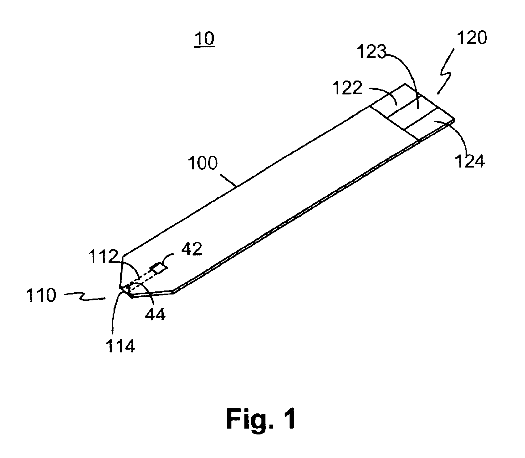
[0030]The preferred embodiment of the present invention is illustrated in FIGS. 1-4. FIG. 1 shows a sensor 10 of the present invention. Sensor 10 has a laminated body 100, a fluid sampling end 110, an electrical contact end 120, and a vent opening 42. Fluid sampling end 110 includes a sample fluid channel 112 between a sampling end aperture 114 and vent opening 42. Sampling end 110 also includes an inlet notch 44. Electrical contact end 120 has three discreet conductive contacts 122,123 and 124.

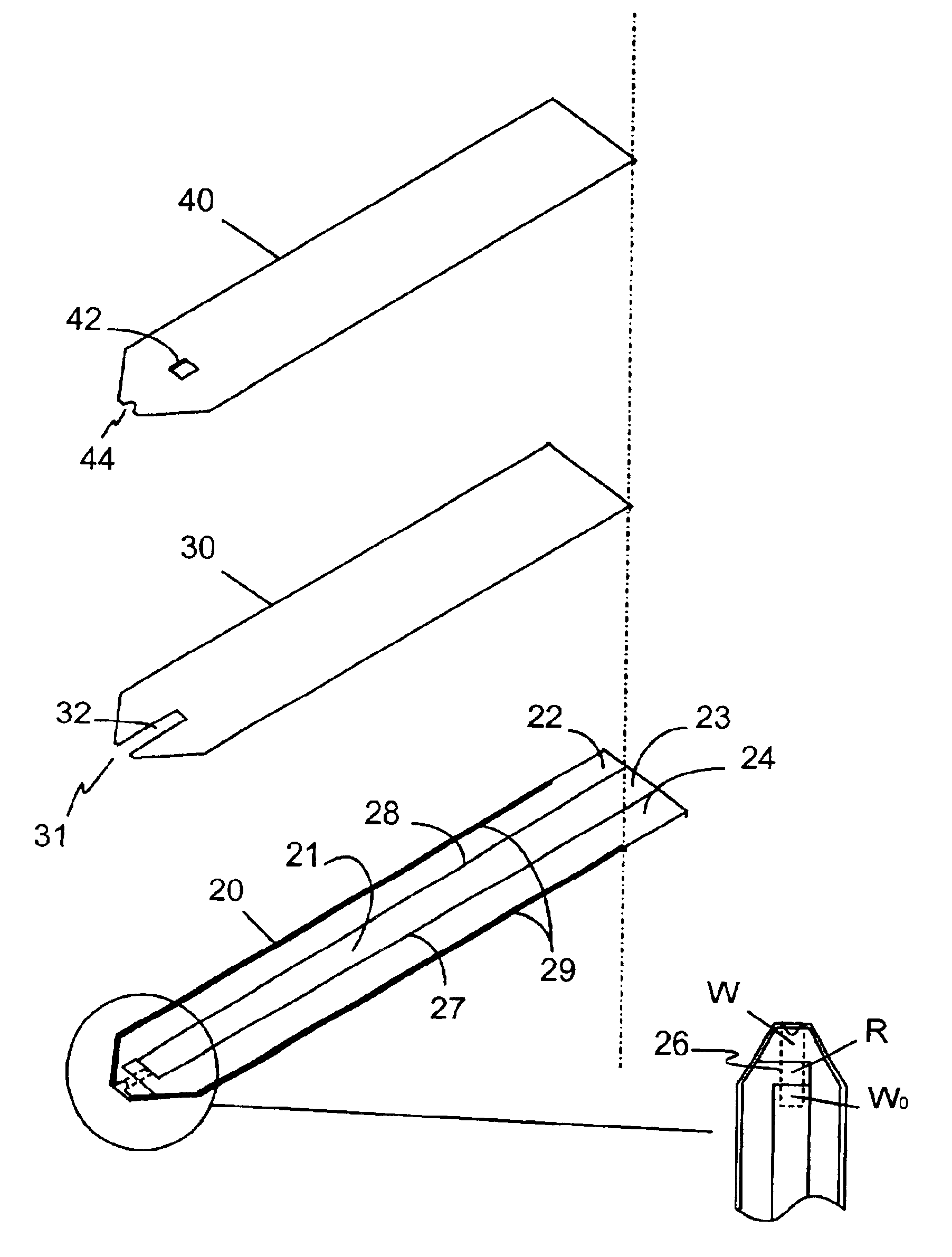
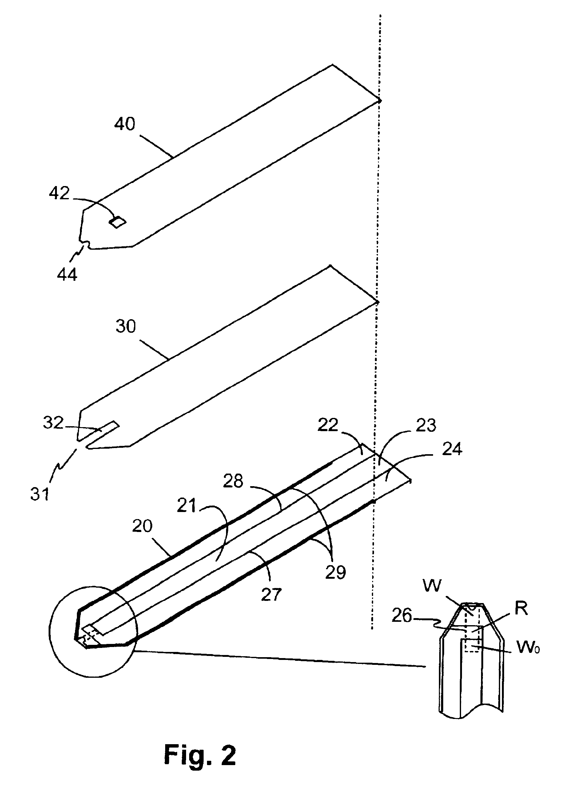
[0031]Referring now to FIG. 2, laminated body 100 is composed of a base insulating layer 20, a middle layer 30, and a top layer 40. All layers are made of a dielectric material, preferably plastic. Examples of a preferred dielectric material are polyvinyl chloride, polycarbonate, polysulfone, nylon, polyurethane, cellulose nitrate, cellulose propionate, cellulose acetate, cellulose acetate butyrate, polyester, acrylic and polystyrene. Base insulating layer 20 has a conductive layer 21 on whic...


PUM

PropertyMeasurementUnit
volumeaaaaaaaaaa
volumeaaaaaaaaaa
wt %aaaaaaaaaa

Abstract

A disposable electrode strip for testing a fluid sample including a laminated strip with a first and second end, a vent, an open path for receiving a fluid sample of less than one microliter beginning from the first end and connecting to the vent, a working electrode, a reference electrode and a pseudo-working electrode embedded in the laminated strip within the open path and proximate to the first end, a reagent matrix coextensive within the open path and covering the three electrodes, and conductive contacts located at the second end of the laminated strip.

Description

BACKGROUND OF THE INVENTION[0001]1. Field of the Invention[0002]The present invention relates generally to electrochemical sensors that can be used for the quantification of a specific component or analyte in a liquid sample. Particularly, this invention relates to a new and improved electrochemical sensor and to a new and improved method of fabricating electrochemical sensors. More particularly, this invention relates to a disposable electrochemical sensor that is inexpensive to manufacture. Even more particularly, this invention relates to a disposable electrochemical sensor that gives accurate readings and requires only about 0.2 microliter of fluid sample. Still even more particularly, this invention relates to disposable electrochemical sensors which are used for performing electrochemical assays for the accurate determination of analytes in physiological fluids.[0003]2. Description of the Prior Art[0004]Biosensors have been used in the determination of concentrations of variou...

Claims


Application Information

Patent Timeline
Patent Type & Authority Patents(United States)
IPC IPC(8): C12Q1/00G01N27/30G01N33/487G01N27/327C12M1/34G01N27/416
CPCC12Q1/001G01N27/3272
Inventor CAI, XIAOHUAWINARTA, HANDANIVO, ANDYYOUNG, CHUNG CHANG
Owner NOVA BIOMEDICAL
Why Eureka
Try Eureka