Stator for a dynamoelectric machine

a technology of dynamoelectric machines and stators, which is applied in the direction of magnets, windings, magnetic bodies, etc., can solve the problems of electromagnetic noise and inability to increase the rigidity of the coil ends, and achieve the effects of reducing electromagnetic noise, increasing rigidity of the coil ends, and exposing the joint portions

Inactive Publication Date: 2005-09-13
MITSUBISHI ELECTRIC CORP
View PDF13 Cites 21 Cited by
  • Summary
  • Abstract
  • Description
  • Claims
  • Application Information

AI Technical Summary

Benefits of technology

[0009]Thus, the rigidity of the coil ends is increased by means of the first electrically-insulating layer, and exposure of the joint portions due to cracking and peeling occurring in the first electrically-insulating layer is prevented by means of the second electrically-insulating layer, thereby providing a stator for a dynamoelectric machine capable of ensuring electrical insulation while reducing electromagnetic noise.

Problems solved by technology

In the conventional stator for an automotive alternator, because a single electrically-insulating layer formed so as to cover the welded portions of the stator winding is constituted by a silicone resin having a small modulus of elasticity, one problem has been that the overall rigidity of the coil ends cannot be increased, therefore increasing electromagnetic noise resulting from vibration of the stator brought about by magnetic attraction arising between the stator and the rotor.

Method used


Image

  • Stator for a dynamoelectric machine
  • Stator for a dynamoelectric machine
  • Stator for a dynamoelectric machine

Examples


embodiment 1

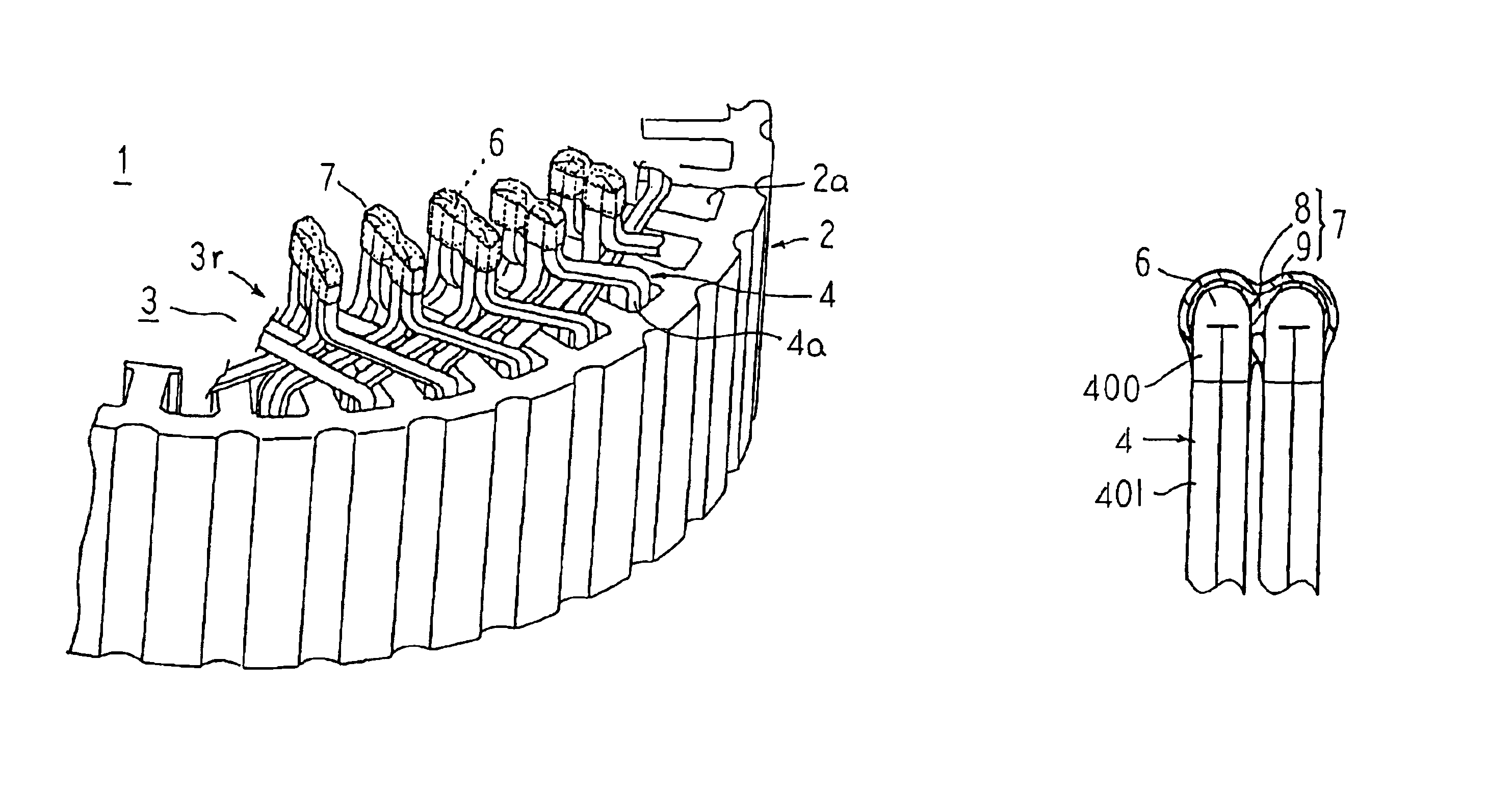
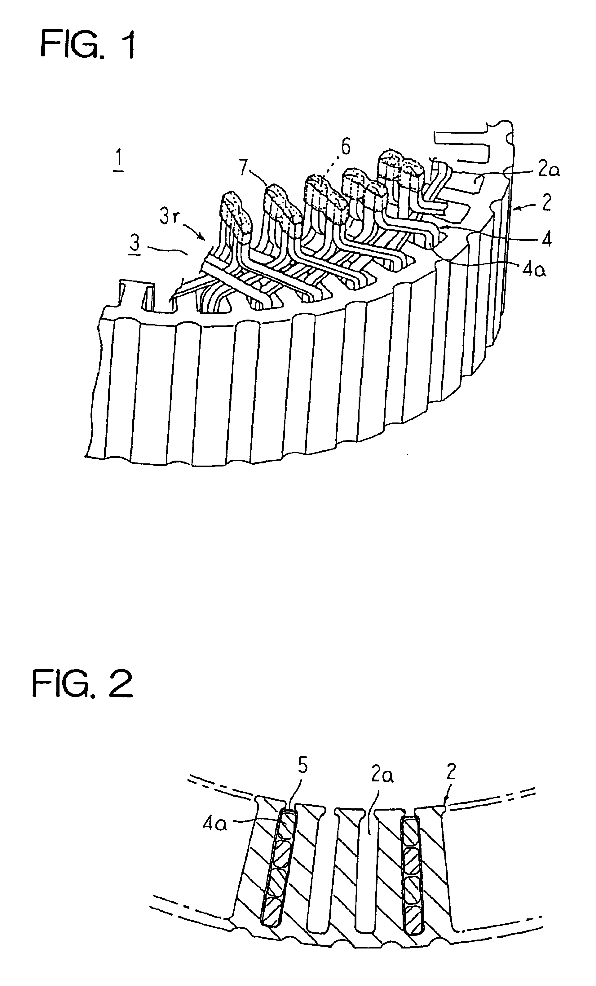
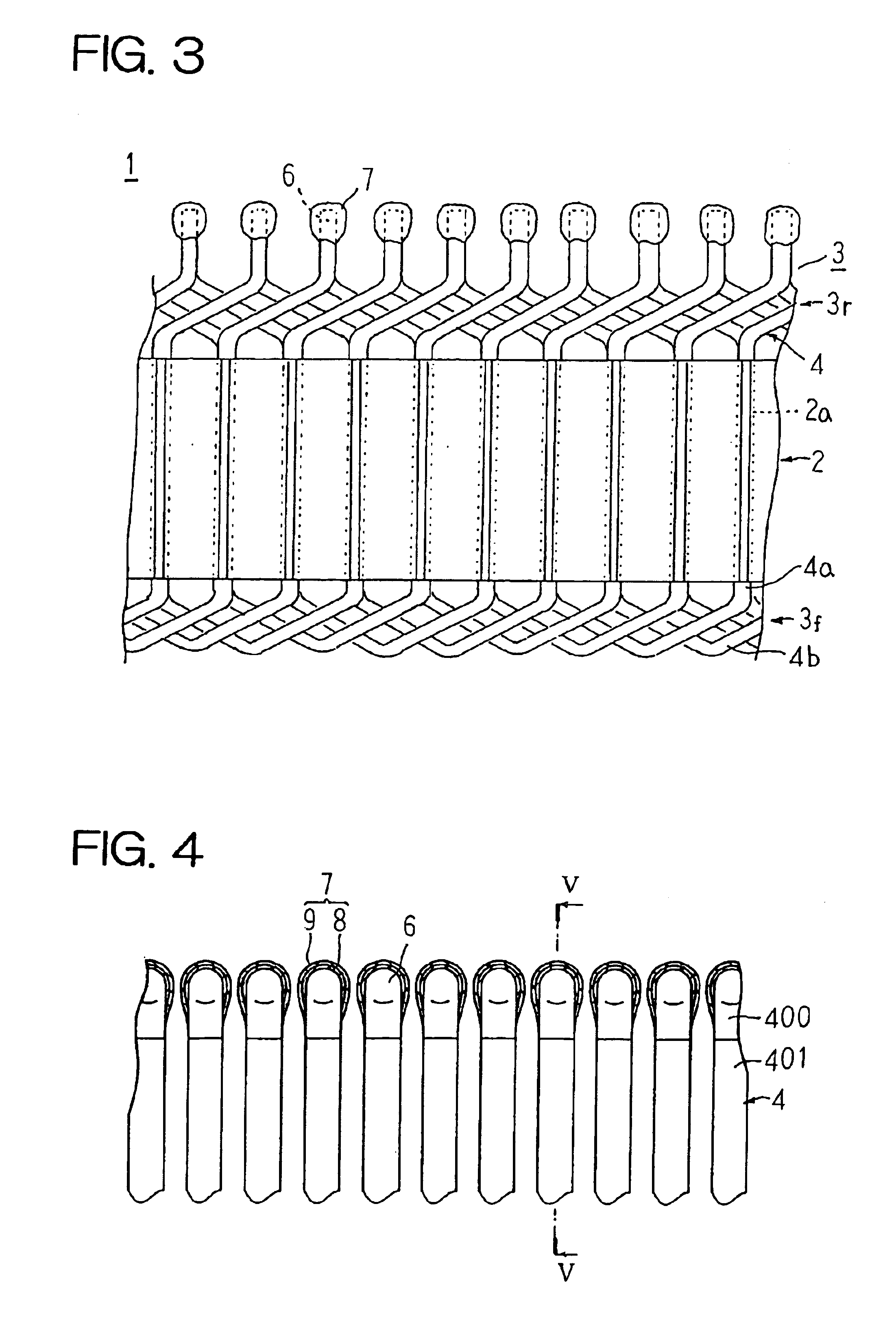
[0028]FIG. 1 is a partial perspective showing a stator for a dynamoelectric machine according to Embodiment 1 of the present invention, FIG. 2 is a partial cross section showing the stator for a dynamoelectric machine according to Embodiment 1 of the present invention, FIG. 3 is a partial plan showing the stator for a dynamoelectric machine according to Embodiment 1 of the present invention viewed from radially inside, FIG. 4 is a cross section explaining an electrical insulation construction of joint portions of a stator winding in the stator for a dynamoelectric machine according to Embodiment 1 of the present invention, FIG. 5 is a cross section taken along line V—V in FIG. 4 viewed from the direction of the arrows, and FIG. 6 is a perspective showing a conductor segment used in the stator winding in the stator for a dynamoelectric machine according to Embodiment 1 of the present invention. Moreover, to facilitate explanation, FIG. 2 shows conductor segments inserted into only on...

embodiment 2

[0056]FIG. 8 is a cross section explaining an electrical insulation construction of joint portions of a stator winding in a stator for a dynamoelectric machine according to Embodiment 2 of the present invention, and FIG. 9 is a cross section taken along line IX—IX in FIG. 8 viewed from the direction of the arrows.

[0057]In Embodiment 2, an electrically-insulating layer 7A is formed into a two-layer construction including: a first electrically-insulating layer 8A composed of an epoxy resin; and a second electrically-insulating layer 9A composed of a silicone resin, the first electrically-insulating layer 8A being applied and shaped so as to cover each of the joint portions 6 (regions integrated by fusion) and to bridge radially- and circumferentially-adjacent pairs of joint portions 6, and the second electrically-insulating layer 9A being applied and shaped so as to cover the first electrically-insulating layers 8A and the regions of the end portions 4c from which the electrically-ins...

embodiment 3

[0062]In Embodiments 1 and 2 above, the stator winding 3 is constructed using U-shaped conductor segments 4 as base strands, but in Embodiment 3, a stator winding 16 is constituted using continuous conductor wires 30 as base strands.

[0063]FIG. 10 is a perspective showing a stator for a dynamoelectric machine according to Embodiment 3 of the present invention, FIG. 11 is a perspective showing the stator for a dynamoelectric machine according to Embodiment 3 of the present invention before mounting caps, FIG. 12 is an end elevation showing a vicinity of an ancillary connection portion in the stator for a dynamoelectric machine according to Embodiment 3 of the present invention viewed from axially outside before mounting caps, and FIG. 13 is an end elevation schematically showing a first single-phase winding phase portion of a stator winding in the stator for a dynamoelectric machine according to Embodiment 3 of the present invention, broken lines in the figure indicating wiring at a f...


PUM

PropertyMeasurementUnit
temperatureaaaaaaaaaa
leakage currentaaaaaaaaaa

Abstract

A stator winding is prepared by inserting U-shaped conductor segments into pairs of slots from a first end surface end of a stator core and welding together end portions of the conductor segments projecting outward at a second end surface end of the stator core. Joint portions between the end portions of the conductor segments are arranged into two rows in an annular shape in a circumferential direction at the second end surface end of the stator core. A first electrically-insulating layer is formed by applying an epoxy resin so as to cover each of the joint portions and to bridge radially-adjacent pairs of the joint portions. A second electrically-insulating layer is formed by applying a silicone resin so as to cover the first electrically-insulating layer and to extend to an electrically-insulating coating on the conductor segments.

Description

BACKGROUND OF THE INVENTION[0001]1. Field of the Invention[0002]The present invention relates to an electrical insulation construction for a stator for a dynamoelectric machine for ensuring electrical insulation by covering a joint portion surface of conductor wires constituting a stator winding with an electrically-insulating resin.[0003]2. Description of the Related Art[0004]In a conventional stator for an automotive alternator, a stator winding is used in which wave windings are formed by inserting U-shaped conductor segments into pairs of slots from a first axial end of a stator core and welding together end portions of the conductor segments projecting outward at a second axial end of the stator core. In addition, a single electrically-insulating layer is formed by applying a silicone resin so as to cover the welded portions of the conductor segments. Since the modulus of elasticity of the silicone resin is small, it is claimed that the occurrence of insulation failure resultin...

Claims


Application Information

Patent Timeline
Patent Type & Authority Patents(United States)
IPC IPC(8): H02K3/38H02K3/50H02K3/32H02K3/34H02K3/04
CPCH02K3/38H02K3/50Y10T29/49073
Inventor OOHASHI, ATSUSHI
Owner MITSUBISHI ELECTRIC CORP
Why Eureka
Try Eureka