Blockage aware zero skew clock routing method

Active Publication Date: 2005-09-13
ORACLE INT CORP
View PDF6 Cites 2 Cited by
  • Summary
  • Abstract
  • Description
  • Claims
  • Application Information

AI Technical Summary

Benefits of technology

[0013]According to the invention, a blockage aware zero skew clock routing method for calculating the distance, and therefore the delay, between two points takes into account any blockages along the path betw

Problems solved by technology

As discussed below, this situation can create a significant complication.
If clock skew becomes too large, the system, at a minimum, will operate inefficiently, typically slower with more errors.
In addition, if the clock skew is more extreme, the system architecture will simply break down and the microprocessor will introduce so many errors that the system will fail.
However, this problem is not new and several mechanisms are in wide use in the art to reduce the clock skew problem including using multiple clock in

Method used


Image

  • Blockage aware zero skew clock routing method
  • Blockage aware zero skew clock routing method
  • Blockage aware zero skew clock routing method

Examples


Embodiment Construction

[0026]The invention will now be described in reference to the accompanying drawings. The same reference numbers may be used throughout the drawings and the following description to refer to the same or like parts.

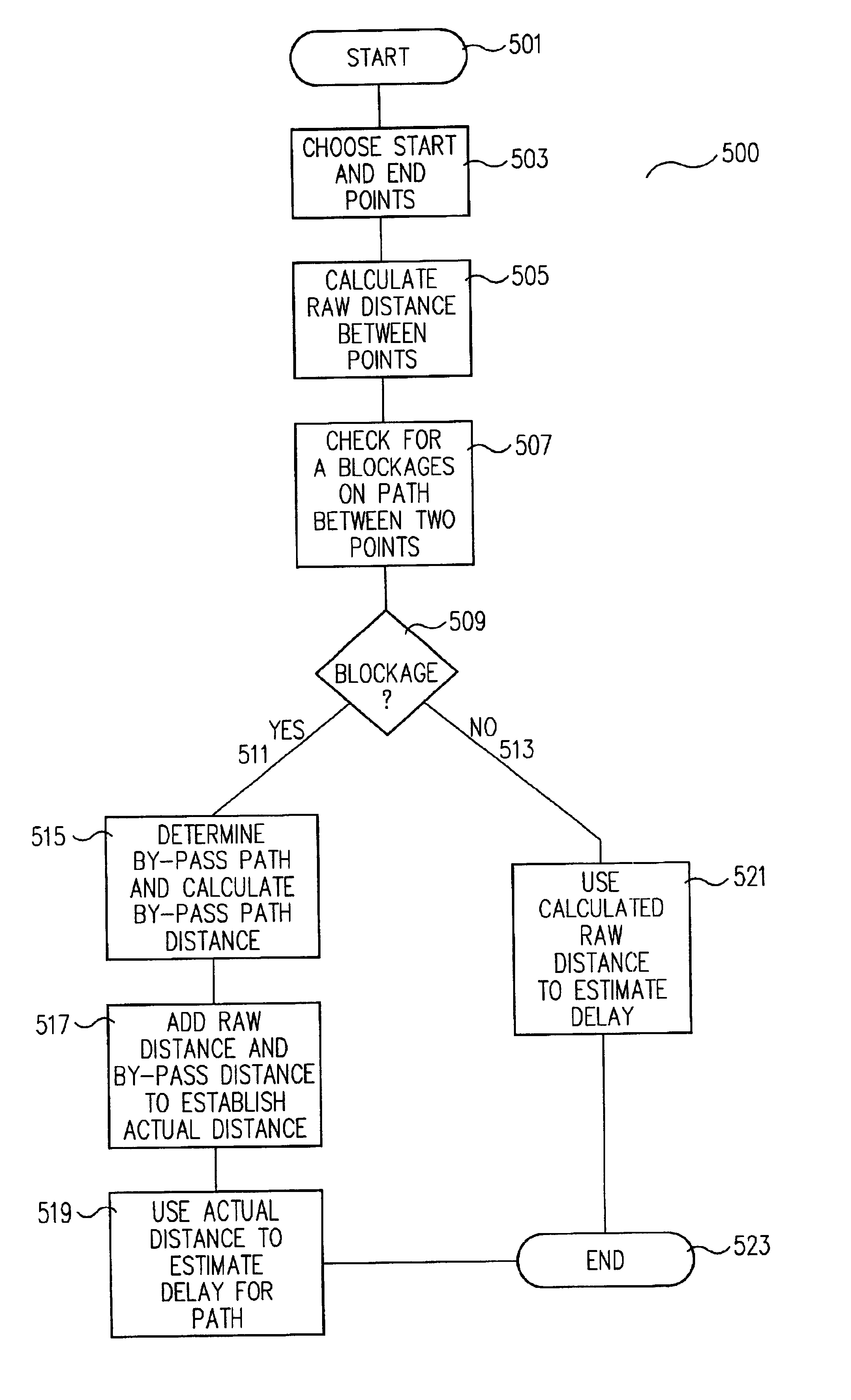
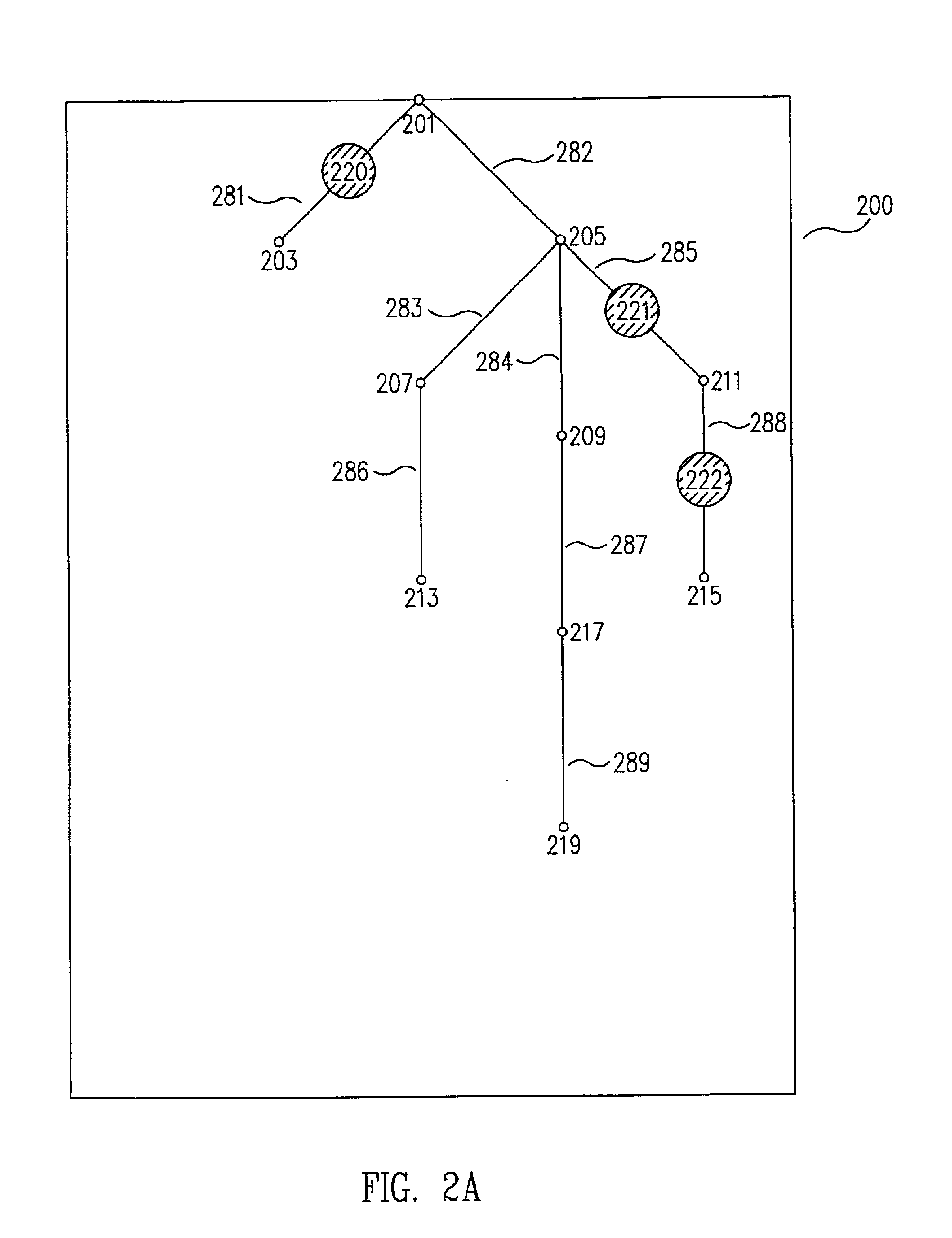
[0027]According to the invention, a blockage aware zero skew clock routing method (400 in FIG. 4 and 500 in FIG. 5) for calculating the distance, and therefore the delay on the same metal layer, between two points takes into account any blockages (220, 221, and 222 in FIGS. 2A and 3A) along the path between the two points and therefore creates a more usable and realistic measure of delay and allows for minimization, or elimination, of clock skew in the system being designed using the method of the invention.

[0028]In one embodiment of the invention, the blockage aware zero skew clock routing method (400 in FIG. 4) begins (401 in FIG. 4) and a first point and second point are designated (403 in FIG. 4). A path between the first and second points is then checked for blockages ...


PUM


Abstract

A blockage aware zero skew clock routing method for calculating the distance, and therefore the delay, between two points takes into account any blockages along the path between the two points and therefore creates a more usable and realistic measure of delay and allows for minimization, or elimination, of clock skew in the system being designed using the method of the invention.

Description

FIELD OF THE INVENTION[0001]The present invention is directed to the field of electronic component design and, more particularly, to methods for minimizing, or eliminating, clock skew in microprocessor design.BACKGROUND OF THE INVENTION[0002]For the present, virtually all mainstream electronic components and systems, such as microprocessors, are synchronous systems employing one or more system clocks that act as the driving force or “heart” of the electronic system. As a result, more often than not, it is critical that a given system clock signal arrive at various points in the system at virtually the same time. As discussed below, this situation can create a significant complication.[0003]FIG. 1 shows a typical length of wire 100 including, from left to right, in the direction shown by arrow 102, points 101, 103 and 105.[0004]As is well known, the physics of conductors and wave propagation dictate two important facts: first, the absolute speed limit for any signal moving from point...

Claims


Application Information

Patent Timeline
IPC IPC(8): G11B20/14G06F17/50
CPCG06F17/5022G06F17/5077G11B20/1403G06F30/33G06F30/394G06F30/3308
Inventor HOJAT, SHERVIN
Owner ORACLE INT CORP
Why Eureka
Try Eureka