
Surveying instrument

a technology of a camera and a body, applied in the direction of instruments, optical elements, angle measurement, etc., can solve the problems of deteriorating performance of the autofocus system

Inactive Publication Date: 2005-09-20
ASAHI KOGAKU KOGYO KK +1
View PDF15 Cites 7 Cited by
  • Summary
  • Abstract
  • Description
  • Claims
  • Application Information

AI Technical Summary

Benefits of technology

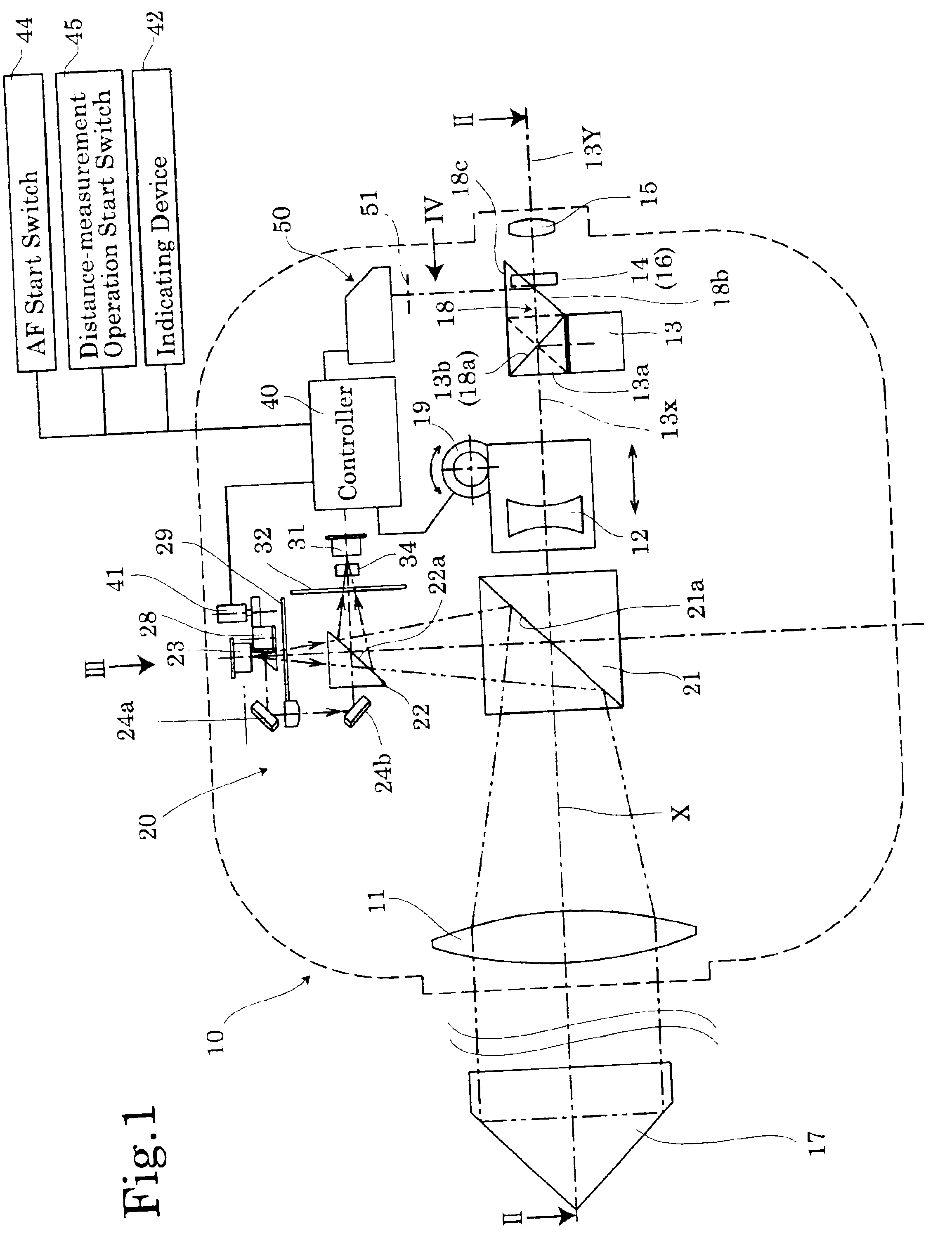
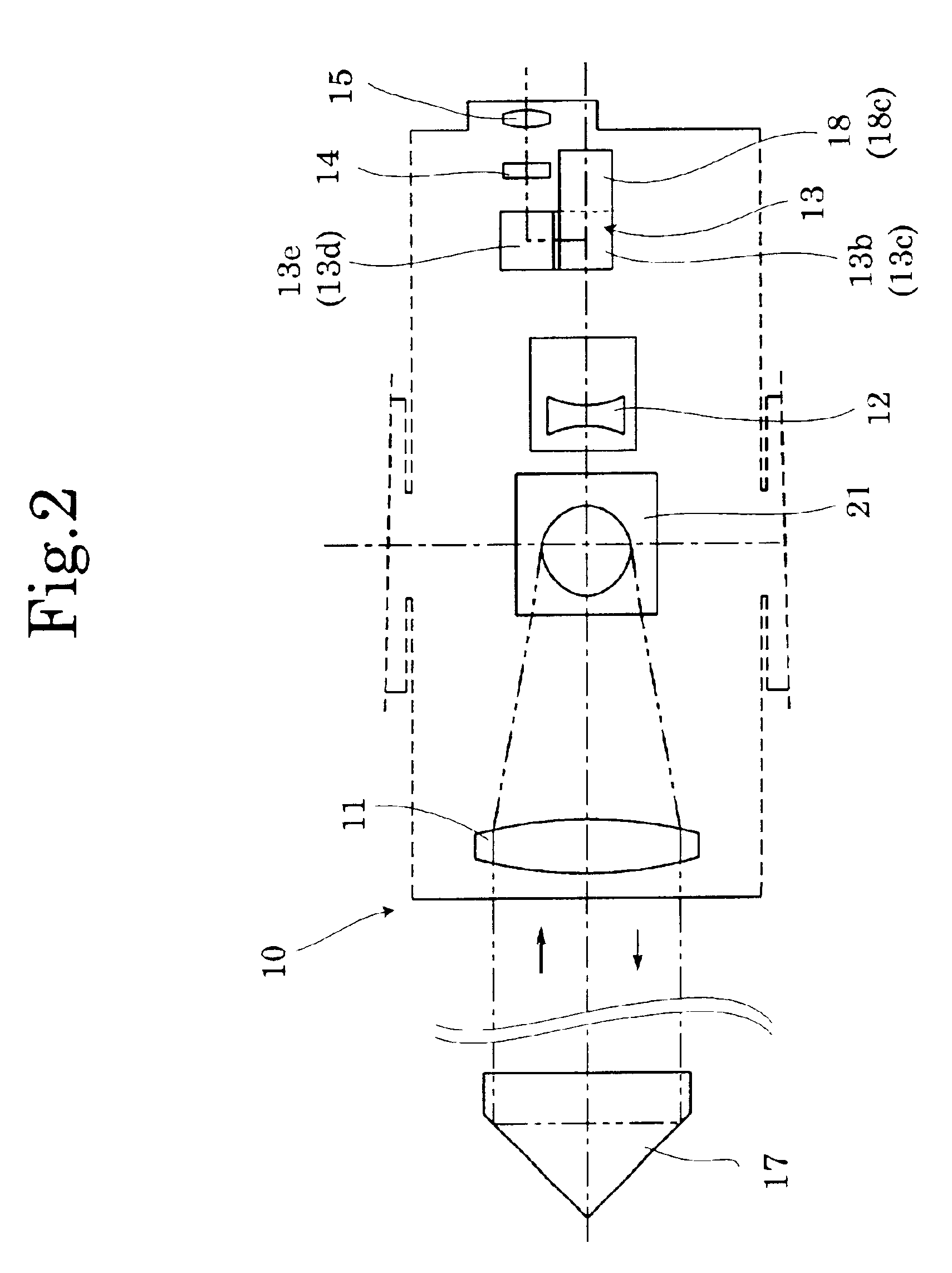
"The present invention provides a surveying instrument that utilizes the performance of its sighting telescope and focus detecting device by preventing ghost images from being formed in the field of view. This is achieved by a light shield device that prevents off-field light from reaching the eyepiece of the sighting telescope. The light shield device can include a light shield mask or a beam splitting prism. The semitransparent film can be formed on the reflection surface of the erecting optical system or on the beam splitting prism. The focus detecting device can be a phase-difference detection or contrast detection focus detecting device. The erecting optical system can include a Porro prism or a roof prism. The sighting telescope can also include a focus adjustment lens. The beam splitting prism can include a right-angle prism."

Problems solved by technology

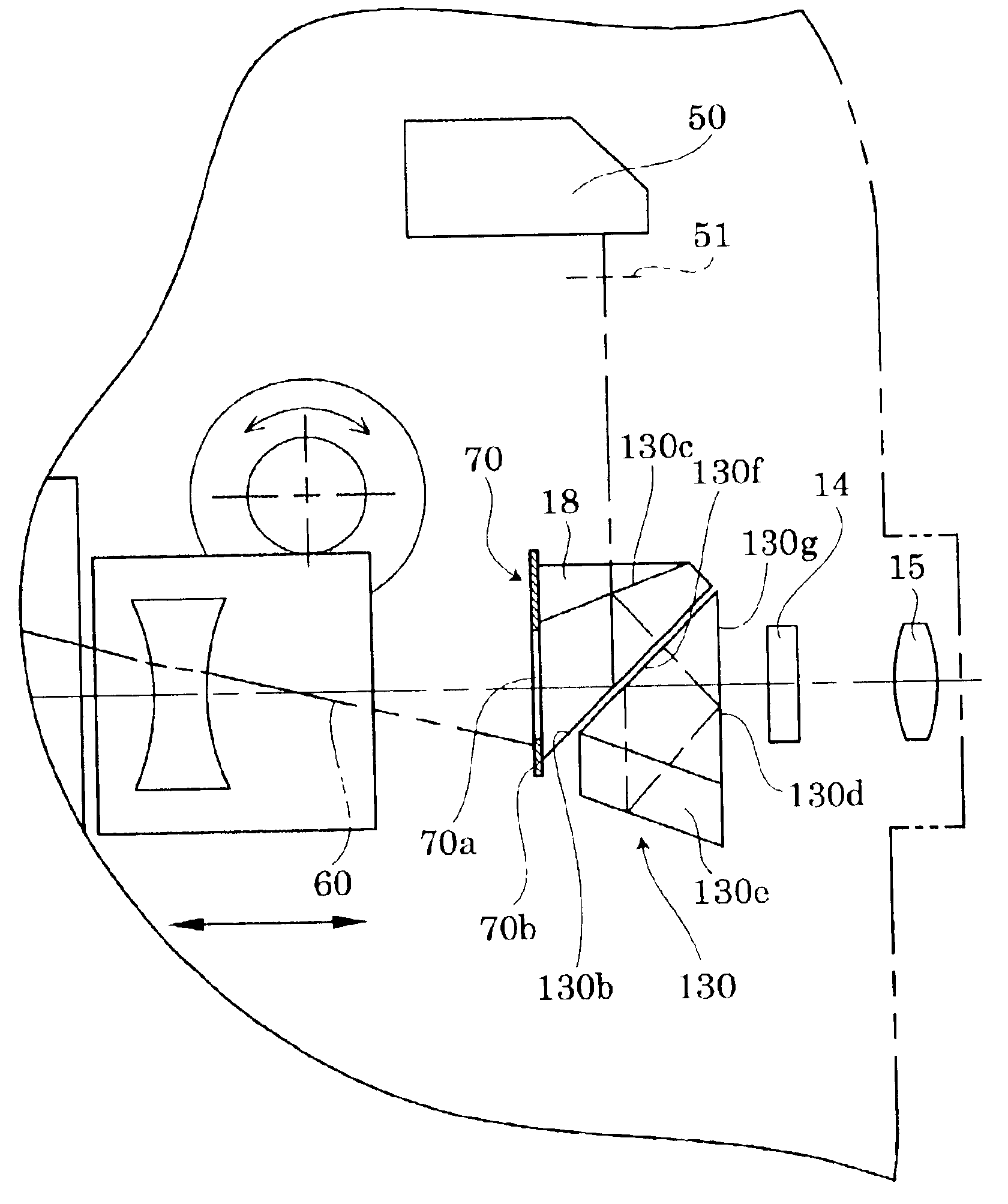
However, in the above described conventional surveying instruments having a sighting telescope, especially with a Porro prism, a ghost image (or a flare spot), which is caused by off-field light (non-image forming light), is seen through the eyepiece of the sighting telescope.
If such off-field light enters the autofocus system via the aforementioned semitransparent mirror, the performance of the autofocus system deteriorates.

Method used


Image

  • Surveying instrument
  • Surveying instrument
  • Surveying instrument

Examples


second embodiment

[0084]FIGS. 11 and 12 show the ghost image formation preventing device. In this embodiment, the Porro prism 13 includes a first prism 13-1 having the incident surface 13a and the first reflection surface 13b, a second prism 13-2 having the second and third reflection surfaces 13c and 13d, and a third prism 13-3 having the fourth reflection surface 13e and the exit surface 13f. The first prism 13-1 and the third prism 13-3 are each cemented to the second prism 13-2. The Porro prism 13 is provided, on a common edge of the cemented surface of the first prism 13-1 and the second prism 13-2, with a recessed portion so that it is positioned in an optical path of the off-field light bundle 60. In the embodiment shown in FIG. 12, a recessed portion 81 is formed on the first prism 13-1. As shown in FIG. 13, a recessed portion 81′ corresponding to the recessed portion 81 can be formed on the second prism 13-2. The recessed portion may be formed on both of the first prism 13-1 and the second p...

fourth embodiment

[0087]FIGS. 17 through 18 show the ghost image formation preventing device. In this embodiment, the first prism 13-1 is shaped to extend forward (leftward as viewed in FIG. 17) so that the incident surface 13a becomes closer to the focusing lens 12. With this structure, the off-field light bundle 60 which is reflected by the first reflection surface 13b is not incident on the second reflection surface 13c, but exits from the bottom of the forwardly-extended portion of the first prism 13-1. The bottom surface of the forwardly-extended portion of the first prism 13-1 can be coated with a matt coating so as to reflect, diffuse or absorb the incident light thereon. As is clearly shown in FIG. 17, the first prism 13-1 of this embodiment is formed to extend toward the focusing lens 12 so that the respective upper ends of the incident surface 13a and the first reflection surface 13b are not connected to each other but are apart from each other by a distance d.

[0088]Each of the above descri...

fifth embodiment

[0090]FIGS. 19 through 21 show the ghost image formation preventing device. In this embodiment, a semitransparent film is formed on the first reflection surface 13b so as to serve as a beam splitter. Moreover, a rectangular light shield mask 90 (see FIG. 20) having an elongated rectangular aperture 90a is fixed between the first reflection surface 13b and the incident surface 18a of the right-angle prism 18. Furthermore, a similar light shield mask 90 (see FIG. 21) is fixed to the exit surface 18c. The light shield mask 90 provided between the first reflection surface 13b and the incident surface 18a reflects, absorbs or diffuses the incident light thereon. If the shape of the aperture 90a is determined so that only the two light bundles 11A and 11B (see FIG. 4) which are respectively passed through two different pupil areas of the AF sensor unit 50 can pass through the aperture 90a, not only the off-field light bundle 60 but any other stray light can be cut off to ensure accuracy o...


PUM


Abstract

A surveying instrument includes a sighting telescope having an objective lens and an eyepiece; an erecting optical system functioning so that an image formed by said objective lens is viewed as an erect image through the eyepiece; and a light shield device, positioned in an optical path extending from an incident surface of the erecting optical system to an exit surface of the erecting optical system, for preventing an off-field light bundle which is incident on the erecting optical system from reaching the eyepiece.

Description

BACKGROUND OF THE INVENTION[0001]1. Field of the Invention[0002]The present invention relates to a surveying instrument having a sighting telescope, and more specifically relates to a surveying instrument having a sighting telescope which is equipped with a device for preventing a ghost image from being formed in the field of view of the sighting telescope.[0003]2. Description of the Related Art[0004]A conventional surveying instrument such as a total station has a function to measure the distance between two points and also horizontal and vertical angles. Such a conventional surveying instrument generally measures the distance between two points with an electronic distance meter (EDM) incorporated in or attached to the surveying instrument. The electronic distance meter incorporates an optical distance meter which calculates the distance via the phase difference between projecting light and reflected light and via the initial phase of internal reference light, or via the time diffe...

Claims


Application Information

Patent Timeline
Patent Type & Authority Patents(United States)
IPC IPC(8): G01C1/00G01C1/02G02B27/00G01S7/481
CPCG01C1/02G01S7/4812G02B27/0018
Inventor SHIRAI, MASAMIWAKAMIYA, SHUNICHIROTAKAYAMA, HOMUKANEKO, KENJI
Owner ASAHI KOGAKU KOGYO KK
Learn More