
Optical element, optical functional device, polarization conversion device, image display apparatus, and image display system

Inactive Publication Date: 2005-09-20
CANON KK
View PDF16 Cites 58 Cited by
  • Summary
  • Abstract
  • Description
  • Claims
  • Application Information

AI Technical Summary

Benefits of technology

[0020]An object of the present invention is to provide a high-performance optical element having minute periodic structures in which

Problems solved by technology

Since it has been difficult to control the wavelength dependence of the amount of birefringence by using conventional birefringence materials, it also has been difficult to control the wavelength dependence of the phase difference between ordinary light and extraordinary light.
When a monochromatic light source such as a laser for emitting a single wavelength is used, the phase difference can be optimized at a designed wavelength; however, in an optical system in which light including various wavelength rays, such as white light, is used, serious problems may occur when a phase plate has the wavelength dependence.
For example, in the case of a liquid crystal projector using light in the visible light region, optical loss occurs at a liquid crystal panel or a color separation device, resulting in decrease in light usage efficiency of the entire system and degradation of image quality.

Method used


Image

  • Optical element, optical functional device, polarization conversion device, image display apparatus, and image display system
  • Optical element, optical functional device, polarization conversion device, image display apparatus, and image display system
  • Optical element, optical functional device, polarization conversion device, image display apparatus, and image display system

Examples


first example

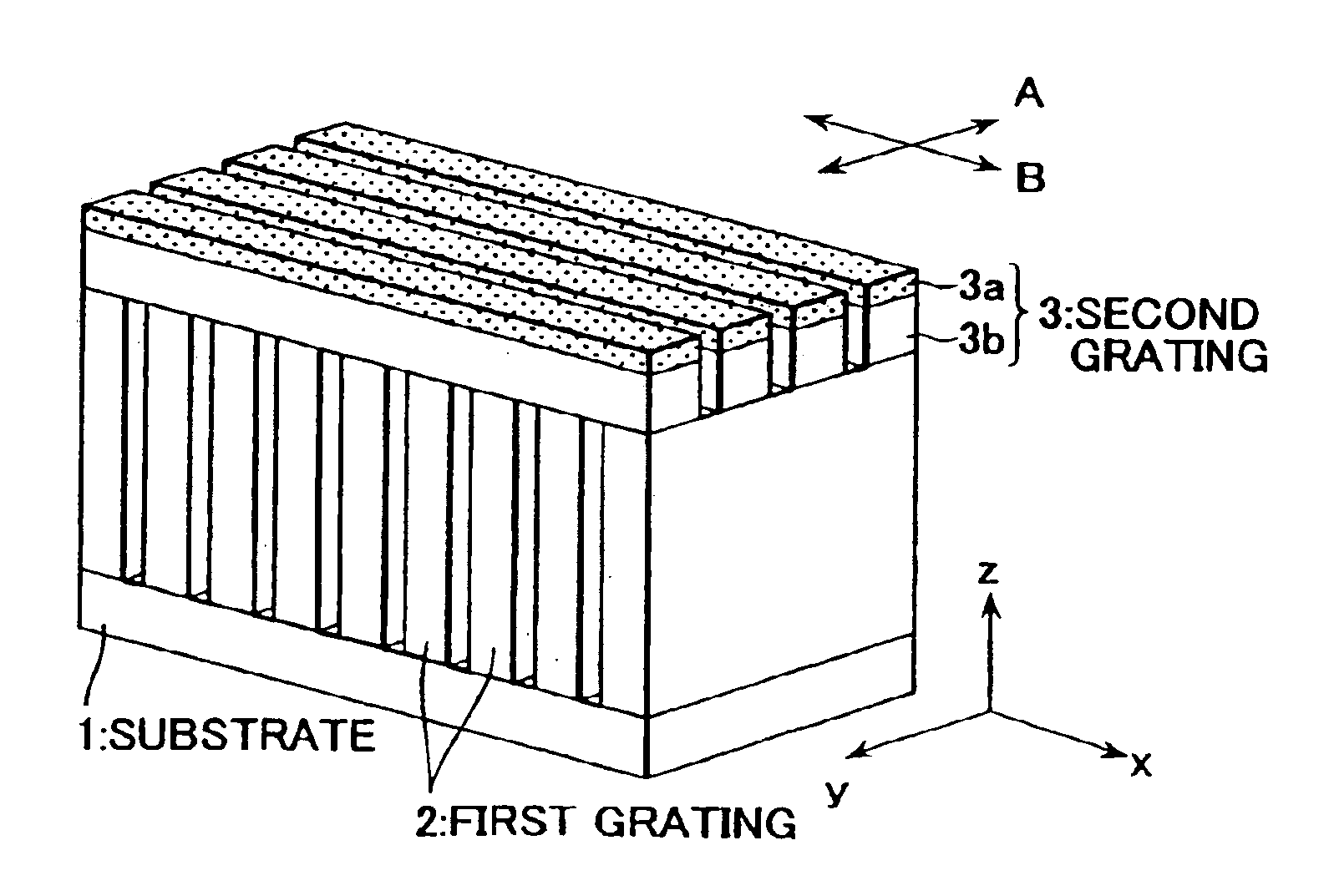
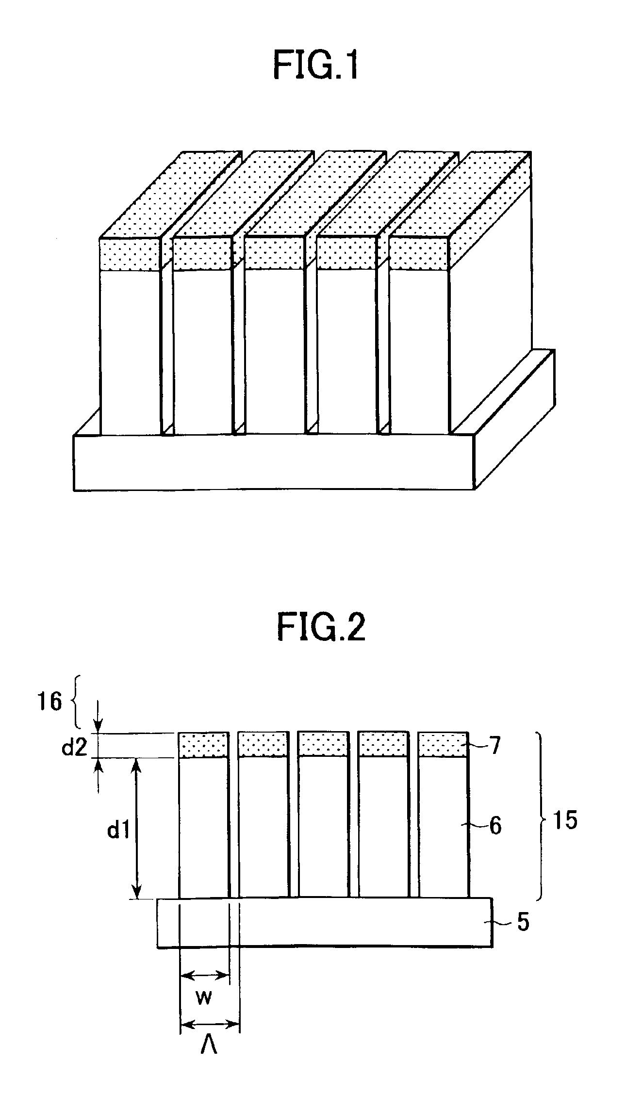
[0089]FIG. 1 is a schematic view showing a phase plate according to a first example. An optical element of this example is a phase plate (λ / 4 plate) having a minute periodic structure. FIG. 2 is a side cross-sectional view of the phase plate shown in FIG. 1. In FIG. 2, reference numeral 5 indicates a substrate, and reference numeral 15 indicates a one-dimensional grating 15 that is a minute periodic structure. The one-dimensional grating is formed of two periodic structures each having a period smaller than the wavelength of usable light. An incident side medium 16 is air. The two periodic structures forming the one-dimensional grating are formed of materials having different refractive indices and dispersibilities from each other. By way of example, the substrate is formed of Ta2O5, and a first periodic structure 6 (hereinafter referred to as “first grating 6”) and a second periodic structure 7 (hereinafter referred to as “second grating 7”) in that order from the substrate side ar...

second example

[0096]Next, a second example of the present invention will be described.

[0097]FIG. 5 is a schematic view showing a phase plate of the second example, FIG. 6 is an x-z plan cross-sectional view of the phase plate in FIG. 5, and FIG. 7 is a y-z plan cross-sectional view of the phase plate in FIG. 5.

[0098]Since being shown by a schematic view which is enlarged in the lateral direction, the phase plate shown in FIGS. 5, 6, and 7, may be different from the actual shape. In the second example shown in FIG. 5, a phase plate (λ / 4 plate) is composed of three gratings. In this second example, the periodic direction of the first grating 6 is perpendicular to those of the second grating 7 and a third grating 8. Hereinafter, a phase plate having the structure as described above is called a multilayer type phase plate. In this example, a multilayer type λ / 4 plate is formed. In this example, the substrate 5 is formed of Ta2O5, and air is used as the incident side medium 16. A material forming the ...

third example

[0106]As a third example of the present invention, a λ / 2 plate for use in a polarization conversion device will be described by way of example. In polarization conversion devices mounted in liquid crystal projectors or the like, by using a polarization beam splitter, non-polarized white light emitted from a light source is converted into two types of linear polarized light having polarization directions different from each other by 90°. In this step, in order to increase the optical usage efficiency, the polarization direction of one type of linear polarized light thus converted is rotated by 90° so as to be the same as that of the other type of linear polarized light, and hence the two types of linear polarized light described above are emitted in the same direction. For rotating the polarization direction by 90°, a λ / 2 plate is used. However, in a conventional λ / 2 plate, the difference in refractive index has wavelength dependence.

[0107]FIG. 11 shows the case in which the λ / 2 plat...


PUM


Abstract

Optical elements have a plurality of periodic structures in which each period is smaller than the wavelength of usable light. Embodiments are provided in which a desired phase difference can be obtained at least at two wavelengths in a used wavelength region, in which periodic directions of a plurality of structures are perpendicular to each other, and in which the difference in refractive index between individual structures for a predetermined polarization component is set to a predetermined value or less.

Description

BACKGROUND OF THE INVENTION[0001]1. Field of the Invention[0002]The present invention relates to optical elements each using a structural birefringence effect provided for minute periodic grating structures whose periods are each smaller than the wavelength of usable light, and relates to optical modulation devices, optical devices, and image display apparatuses, which are provided with the optical elements described above.[0003]2. Description of the Related Art[0004]Hitherto, as birefringence materials, for example, crystal materials such as calcite and quartz, liquid crystal materials, and plastic and polymeric materials having birefringence effects have been known. These birefringence materials have been used, for example, for phase plates (quarter wave plates, half wave plates) and low pass filters. In recent years, the birefringence materials have been increasingly important as materials used for various products such as liquid crystal projectors, liquid crystal displays, digit...

Claims


Application Information

Patent Timeline
IPC IPC(8): G02B5/30G02B5/18
CPCG02B5/1809G02B5/3083
Inventor HOSHI, HIKARU
Owner CANON KK
Features
  • Generate Ideas
  • Intellectual Property
  • Life Sciences
  • Materials
  • Tech Scout
  • Unparalleled Data Quality
  • Higher Quality Content
  • 60% Fewer Hallucinations
Learn More