Method and apparatus for generating a radio frequency signal

a radio frequency signal and radio frequency technology, applied in the field of linear amplification of radio frequency signals, can solve the problems of inherently non-linear devices of rf power amplifiers, interference distortion with signals on other channels, difficult and expensive production of analog elements with excellent matching characteristics, etc., to achieve the effect of improving linearisation

Inactive Publication Date: 2005-09-20
TELEFON AB LM ERICSSON (PUBL)
View PDF9 Cites 41 Cited by
  • Summary
  • Abstract
  • Description
  • Claims
  • Application Information

AI Technical Summary

Benefits of technology

[0028]It is an object of the invention to provide an improved linearisation method by using digital predistortion in both wide b

Problems solved by technology

Intermodulation distortion will interfere with signals on other channels.
RF power amplifiers are inherently non-linear devices since they generate unwanted intermodulation products, which manifest themselves as spurious signals in the amplified output signal, separate and distinct from the input signal.
However, analog elements with excellent matching characteristics are very difficult and expensive to produce.
Analog predistortion typically has a limited dynamic (operation)range and is therefore only able to produce limited performance improvements.
Analog predistortion, however, can operate over large bandwidths.
However, because the predistortion occurs at baseband, it needs to be converted to radio frequency before it can be amplified.
The frequency conversion, however, takes place in the analog domain, which by its nature destroys the perfect matching capabilities of the digital domain.
This results in that also digital predistortion becomes limited in respect of performance and bandwidth compared to analog predistortion.
Analog and digital predistortion linearisation are typically implemented as standalone techniques, because of practical implementation problems arising from the fact that the two solutions require different architectures for implementation.
In both examples, the digital baseband processing parts and the PA module are physically separated, which introduces practical implementation problems.
This results in the overall efficiency being degraded, also when combining the two methods.
The solution is also quite complicated, requiring a large amount of componen

Method used


Image

  • Method and apparatus for generating a radio frequency signal
  • Method and apparatus for generating a radio frequency signal
  • Method and apparatus for generating a radio frequency signal

Examples


Embodiment Construction

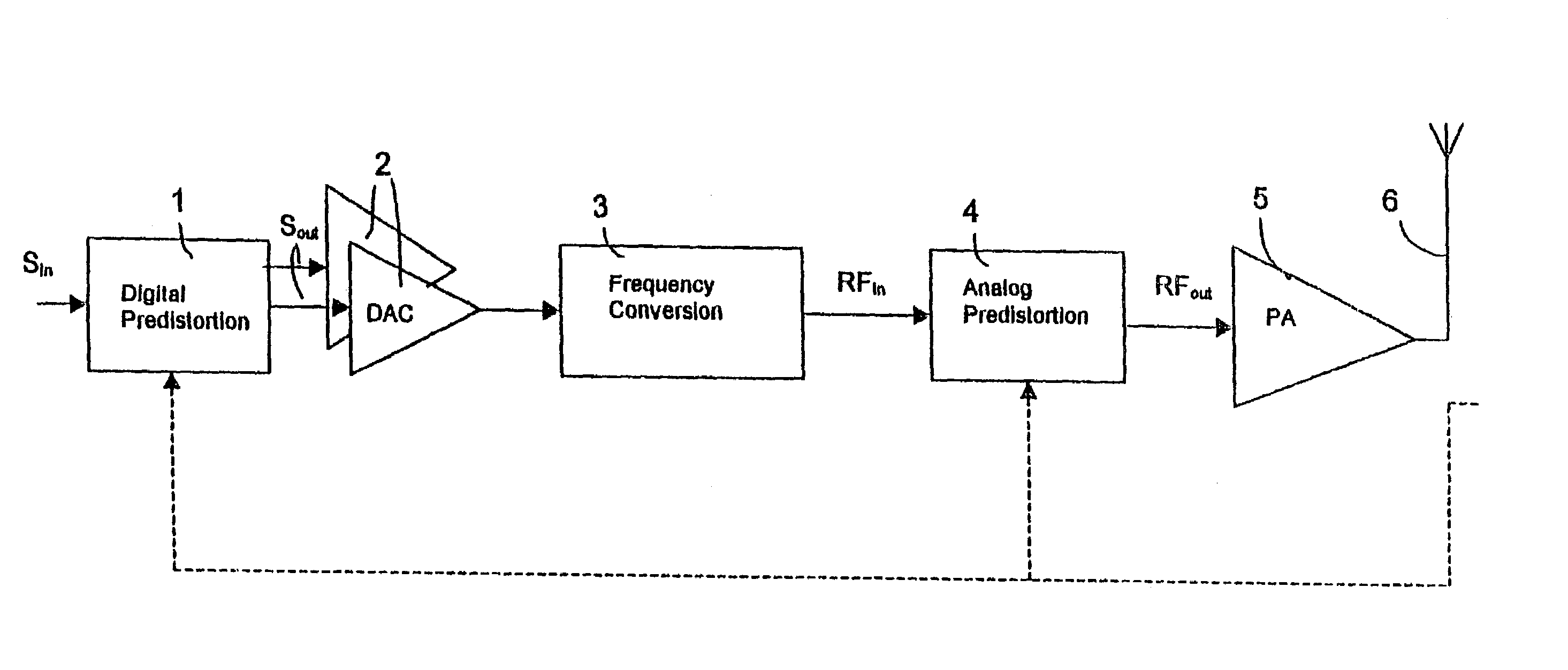
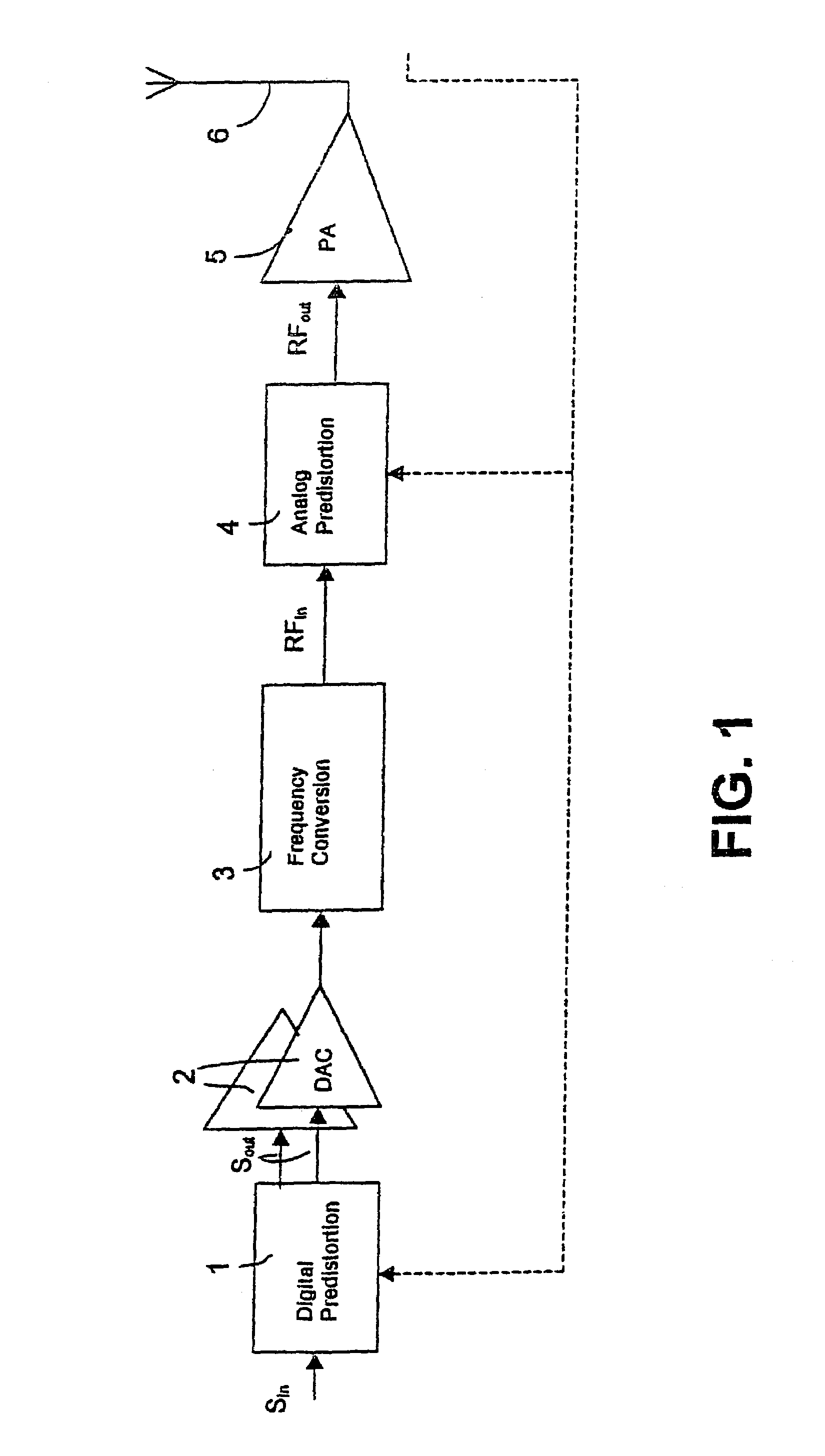
[0051]With reference to FIG. 1, a digitized complex baseband input signal Sin is first predistorted, as indicated by block 1, to produce a complex baseband digital predistorted output signal Sout. More particularly, this is done in a manner to be complementary with respect to a combination of an analog predistorter and a power amplifier, discussed further below and indicated by blocks 4 and 5, respectively. This combination of an analog predistorter and a power amplifier can be thought of as forming a linear power amplifier.

[0052]The complex baseband digital predistorted signal Sout is then converted to an analog signal by two Digital to Analog Converters (DAC), indicated at 2. Alternatively, although not shown in FIG. 1, the baseband digital predistorted signal Sout can be first digitally frequency converted, before being converted to an analog signal via a single DAC.

[0053]The output from the DAC is then frequency converted by frequency conversion circuits, indicated by block 3, t...


PUM


Abstract

The invention relates to linearization of a radio frequency (RF) power amplifier (5) by predistortion. Digital predistortion is performed (1) on received digitized base-band input signals to compensate for amplifier distortion. The resulting signal is converted to an analog signal via two D/A converters (2), after which analog frequency conversion is performed (3) on the analog signal to achieve a radio frequency (RF) signal. This radio frequency signal is exposed to analog predistortion (4) and thereafter amplified by the power amplifier.

Description

[0001]This application is the US national phase of international application PCT / SE00 / 02312 filed 23 Nov. 2000, which designated the US.TECHNICAL FIELD[0002]The present invention relates to a method and an apparatus for generating a radio frequency (RF) signal, and more particularly to linear amplification of radio frequency signals.BACKGROUND ART[0003]In a radio base station, there is a need for a high power amplifier in the transmitter section to provide each radio channel with enough power to reach the outer limits of a cell covered by a base station.[0004]When using the same amplifier for simultaneous amplification of several information signals modulated on different carrier waves or when using linear modulation, such as QAM (Quadrature Amplitude Modulation), high amplifier linearity is required. This is because it is essential in this case to maintain all phase and amplitude positions of the signal components involved in the amplification. Otherwise inter-modulation will occur...

Claims


Application Information

Patent Timeline
IPC IPC(8): H03F1/32H04B7/005
CPCH03F1/3241H04B1/62
Inventor LEYONHJELM, SCOTT ALLAN
Owner TELEFON AB LM ERICSSON (PUBL)
Why Eureka
Try Eureka