System and method for sensing torque on a rotating shaft

Inactive Publication Date: 2005-09-27
ROCKWELL AUTOMATION TECH
View PDF14 Cites 50 Cited by
  • Summary
  • Abstract
  • Description
  • Claims
  • Application Information

AI Technical Summary

Benefits of technology

[0010]The present invention provides for an optical sensing system that facilitates measuring torque in a shaft and gathers significantly more data than the aforementioned prior art systems, and accordingly provides a more comprehensive analysis with respect to shaft analysis. Light emitted from a light source is directed through a photo-elastic material in an axial direction along a rotating shaft, thus allowing for a significantly greater amount of coverage area from which the sensor can detect torsional strain, for example. The optical sensing system of the subject invention can also be used for high-frequency load sensing, lateral load sensing, and surface monitoring as well as measuring rotational speed, displacement, acceleration, vibration, temperature, stress, etc. Through use of external storage and display components, properties of the shaft (e.g., torque, rotational speed, displacement . . . ) can to stored and / or displayed, wherein the properties to be stored and / or displayed are predefined and / or user defined and / or dynamically determined based on context as well as user state. Thus, the invention provides a flexible and robust system and method for determining torque on a rotating shaft while minimizing weight and cost of a corresponding sensing device.
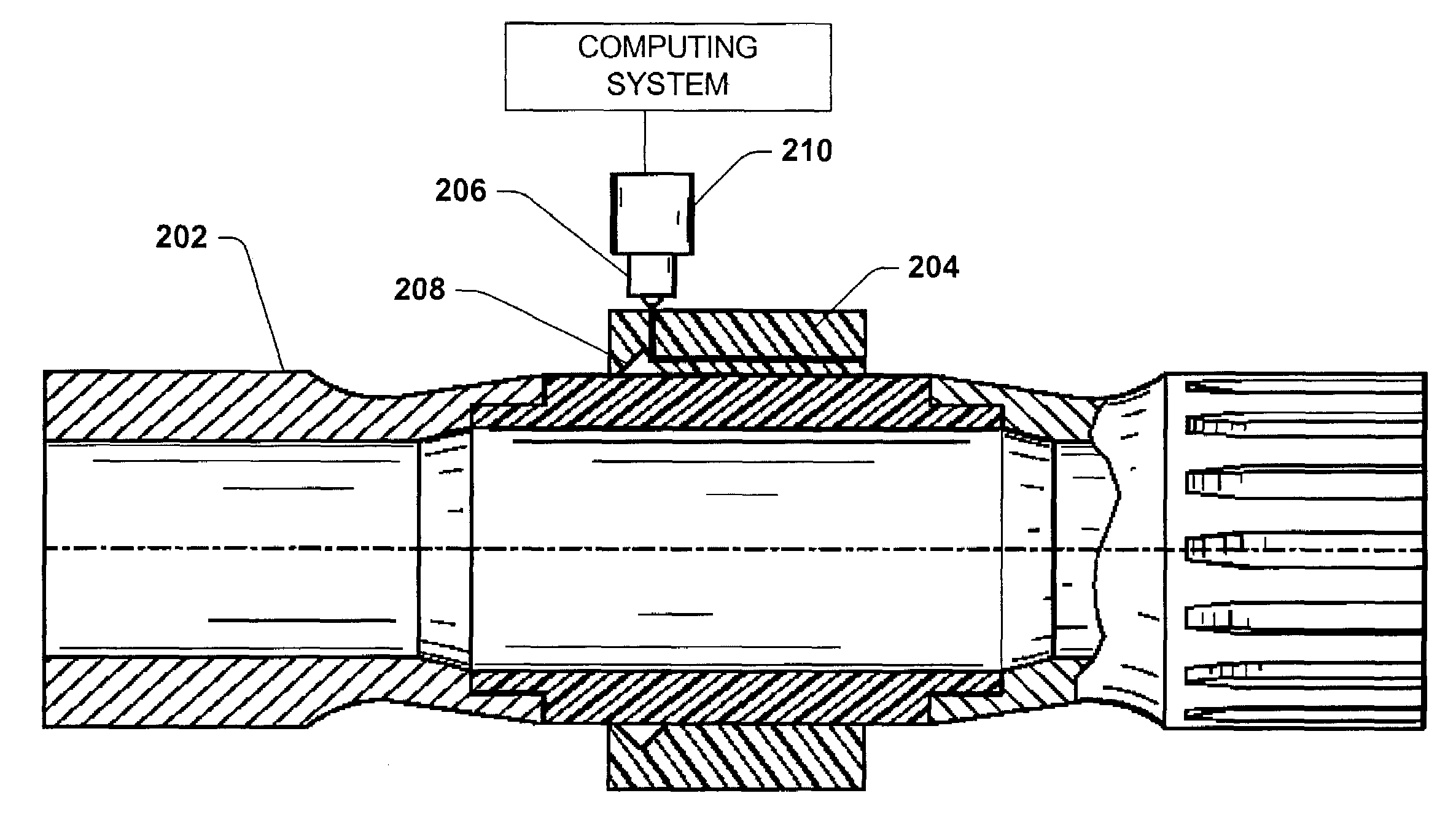
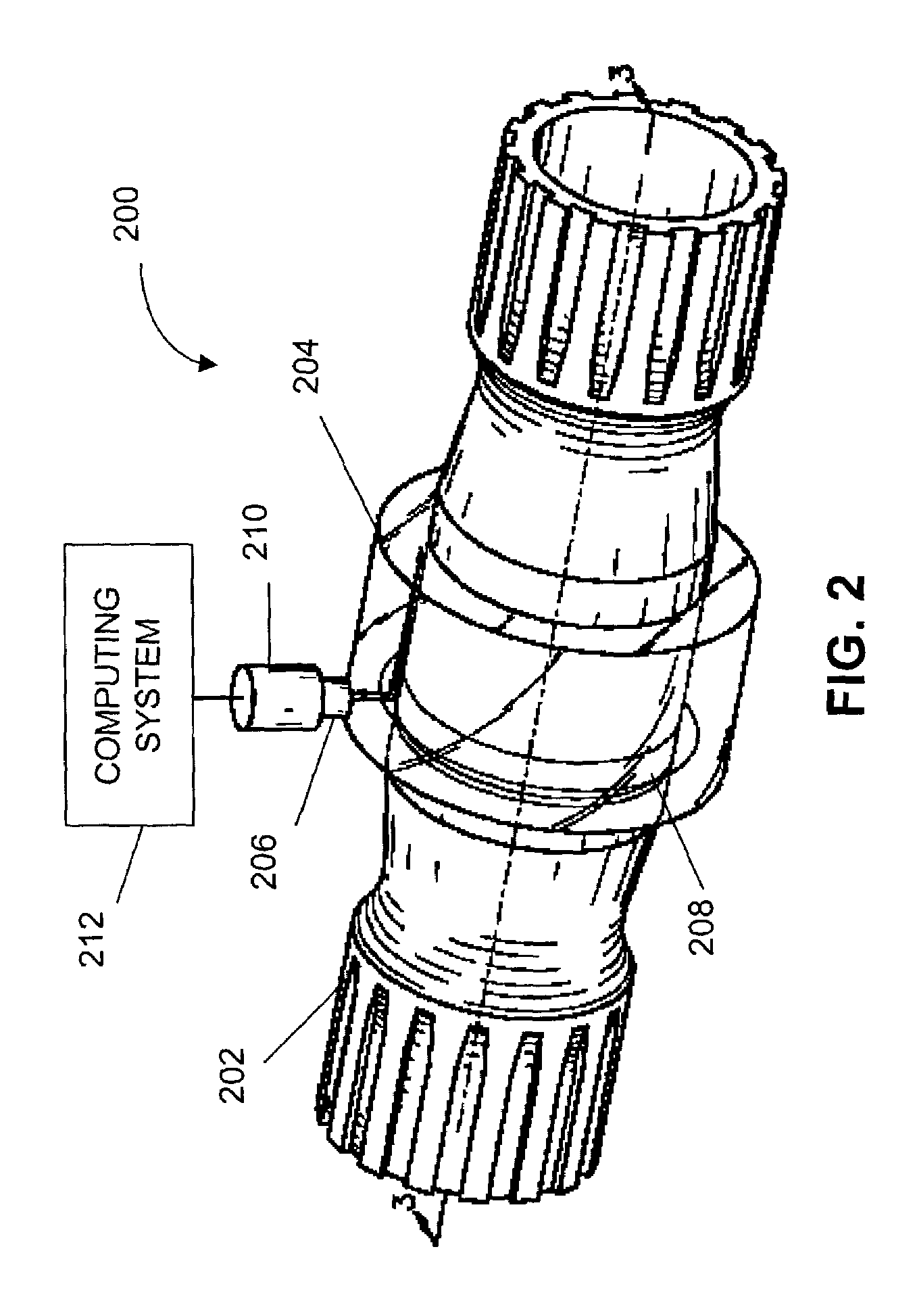
[0011]In accordance with one aspect of the present invention, a portion of a rotating shaft is encircled by a sleeve of photo-elastic material, wherein the photo-elastic sleeve is attached to the shaft. For example, the photo-elastic sleeve can be cast, machined, or even sprayed onto the shaft. A light source is employed to deliver light that will travel along the axis of the shaft through the photo-elastic sleeve. The light source can be placed at any suitable angle to the rotating shaft, so long as the light delivered is redirected through the photo-elastic sleeve along the axis of the shaft. For instance, a light source can be configured to deliver light perpendicularly to the shaft into the photo-elastic sleeve, wherein the light is redirected by a reflective notch (e.g., v-groove) cut at an angle (e.g., 45°) to the light source, thereby redirecting the light along the axis of the shaft. V-groove faces can optionally be covered with a thin strip of reflective material (e.g., Mylar®) to provide a specular surface with minimal light distortion. At least one end of the collar of the photo-elastic material can be coated with a reflective substance (e.g., aluminum filled epoxy), thus requiring a beam of light emitted from a light source to reflect back along the same path. Requiring a beam of light to traverse the photo-elastic sleeve twice (e.g., once prior to reaching the reflective edge and once upon reflection) results in a more thorough analysis of strain on the shaft. Since a number of fringes (discussed in greater detail below) increases linearly with optical path length, sensitivity of the optical sensing system is also increased as a function of length of the photo-elastic material. It is to be understood, however, that a reflective substance on a collar of the photo-elastic sleeve is not required to practice the invention, as strain on the shaft can be determined when a beam of light passes through an end photo-elastic sleeve an data collected at such end as compared to the light reflecting backward from such end.
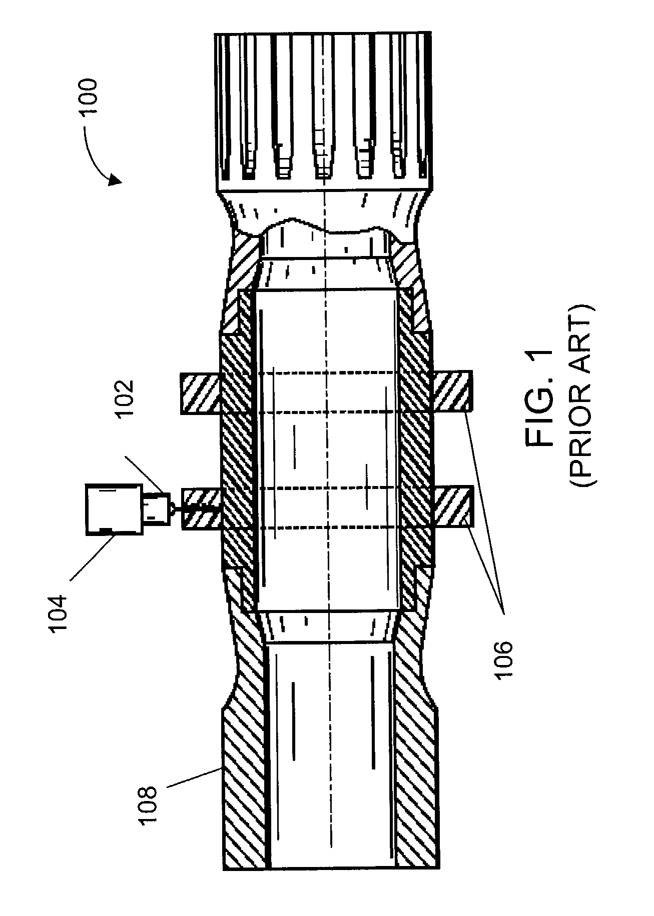
[0013]The subject invention can be implemented with any rotating shaft that may incur strain from driving a load. For example, the invention could be employed to determine the torque and strain on a turbine drive shaft, a drive shaft on a truck or automobile, a shaft driving a helicopter blade, etc. The invention can also be coupled to a control system, thereby protecting the shaft from failure due to excessive torque. A control system can also be employed in connection with the present invention to control operation of the shaft by utilizing one or more parameters that can be sensed by the sensor (e.g., rotational speed, acceleration, displacement, vibration, temperature, torque, stress . . . ). For example, this provides an effective method for constant torque control. Furthermore, the invention can be used in connection with a diagnostic system, wherein upon reaching a critical point of strain the diagnostic system will inform an operator that repair or replacement of the shaft is necessary. In another embodiment, a prognostic system utilizing inferential techniques can be employed to predict a time in the future when repair or replacement of the shaft will be necessary. Lastly, high frequency analysis of the torque signal using established frequency domain or joint time-frequency methods can be a very effective, low cost, diagnostic tools. Also, the broad inspection sensing area can provide a capability to inspect composite joint(s) dynamics.

Problems solved by technology

Robust, affordable, lightweight sensing systems for obtaining data regarding a rotating shaft (specifically torque), however, are presently non-existent.
Rotating shafts driving a load are susceptible to torsion strain.
Continuous strain on the shaft will eventually result in machine inefficiency and / or shaft malformation and / or breakage.
Dynamic torque (strain) fluctuations can cause mechanical and fatigue damage as well as accelerate machine failure.
However, conventional torque sensors are large, costly, and heavy devices.
Furthermore, the conventional shaft torque sensing system in the example above would cost at least five thousand dollars, be susceptible to failure due to shock loads, and take up valuable aircraft space and payload capacity.
Conventional sensing systems that consider angular displacement difference between two ends of a rotating shaft typically involve costly and complex optics and mechanical interconnect equipment.
Lastly, optical sensing systems can provide high frequency torque signals unobtainable with conventional torque sensor(s).

Method used


Image

  • System and method for sensing torque on a rotating shaft
  • System and method for sensing torque on a rotating shaft
  • System and method for sensing torque on a rotating shaft

Examples


Embodiment Construction

[0034]The present invention is now described with reference to the drawings, wherein like reference numerals are used to refer to like elements throughout. In the following description, for purposes of explanation, numerous specific details are set forth in order to provide a thorough understanding of the present invention. It may be evident, however, that the present invention may be practiced without these specific details. In other instances, well-known structures and devices are shown in block diagram form in order to facilitate describing the present invention.

[0035]As used in this application, the terms “component” or “system” are intended to refer to a computer-related entity, either hardware, a combination of hardware and software, software, or software in execution. For example, a computer component can be (but is not limited to) a process running on a processor, a processor, an object, an executable, a thread of execution, a program, and / or a computer. By way of illustrati...


PUM


Abstract

A system and method relating to the measuring of torque in a rotating shaft is provided. An optical torque sensing system comprises a rotating shaft, wherein a sleeve of photo-elastic material overlays a portion of the shaft. A light emitting component delivers light into the photo-elastic material, wherein the light delivered by the light emitting component is directed through the photo-elastic material along an axis of the rotating shaft. A capturing component captures the light that exits the photo-elastic material. The exiting light comprises fringe pattern data, and a computing system computes torsion strain of the shaft based at least in part on the fringe pattern information.

Description

CROSS-REFERENCE TO RELATED APPLICATIONS[0001]This application claims the benefit of U.S. Provisional Application Ser. No. 60 / 371,104 entitled Systems and Methodologies for Enhancing Machine Reliability, filed on Apr. 9, 2002—the entirety of this application is incorporated herein by reference.TECHNICAL FIELD[0002]The present invention generally relates to optical sensors employed in conjunction with sensing a photo-elastic effect. In particular, the present invention relates to a system and method for obtaining and analyzing data regarding a rotating shaft via an optical torque sensor.BACKGROUND OF THE INVENTION[0003]Sensors can be found everywhere in today's society—heat sensors are utilized in a common thermostat to activate / deactivate heating and cooling units. Light sensors can be used to govern when to turn on and off automobile headlights (e.g., if the sensor does not receive a predetermined minimum amount of light, a control unit will activate headlights). Even an alarm clock...

Claims


Application Information

Patent Timeline
IPC IPC(8): G01L3/02G01L1/24G01L3/12
CPCG01L3/12
Inventor DISCENZO, FREDERICK M.
Owner ROCKWELL AUTOMATION TECH
Why Eureka
Try Eureka