Superconducting open MRI magnet with transverse magnetic field

a transverse magnetic field, superconducting technology, applied in the field of magnets, can solve the problems of large stray field, no access to patients, and distressing feeling of claustrophobia of some patients, and achieve the effect of small stray field, low requirement for conductors, and high homogeneity

Inactive Publication Date: 2005-09-27
OXFORD MAGNET TECH LTD
View PDF9 Cites 13 Cited by
  • Summary
  • Abstract
  • Description
  • Claims
  • Application Information

AI Technical Summary

Benefits of technology

[0012]The magnet coils can therefore comprise substantially identical coil subassemblies for each quadrant of the magnet assembly thereby simplifying the manufacture of the magnet assembly. In the simplest form of the invention, there would be four coil subassemblies.
[0015]A central part or corresponding parts to the cryostat, facing inwardly and centrally around a patient body part of interest can conveniently be recessed to allow space for a gradient coil and an RF coil. Such space could also be conveniently be employed for the positioning of shims for the primary magnet.
[0017]Thus in one aspect the present invention provides a magnet suitable for a magnet resonance imaging apparatus which provides a strong magnetic field of high homogeneity and a small stray field, with a low requirement for conductor. In magnets where this conductor consists of a superconductor, such as NbTi, this reduction in amount of conductor will lead to a substantial saving in weight and cost.

Problems solved by technology

Although the length of this bore tube is typically 1.6 m or less it can cause a feeling of claustrophobia which is extremely distressing to some patients.
Furthermore, such a design does not give any access to the patient, which may be essential for interventional procedures, or when the proximity of a companion is required to put the patient at ease.
However, the disadvantage of such a design is that for a given central field strength, a large stray field is produced.
However, an increase of the size of the shielding coils will reduce the central field.
Because large amounts of iron are required, these known C-shaped magnets are very heavy, especially for high field magnets which require many tonnes of iron to define the flux return path.
Huson et al further discloses the use of shielding coils for constraining the magnetic return flux but the amount of conductor used, and hence the cost, is high.
The structure must therefore be substantial, and provides a significant impediment to free access to the imaging volume,

Method used


Image

  • Superconducting open MRI magnet with transverse magnetic field
  • Superconducting open MRI magnet with transverse magnetic field
  • Superconducting open MRI magnet with transverse magnetic field

Examples


Embodiment Construction

[0028]There will now be described by way of example the best mode contemplated by the inventor for carrying out the invention. In the following description numerous specific details are set forth in order to provide a thorough understanding of the present invention. It will be apparent, however, to one skilled in the art, that the present invention may be practised without using these specific details. In other instances, well known methods and structures have not been described in detail so as not to obscure the present invention unnecessarily. For example, whilst the figures show the patient access plane or midplane to be in the horizontal plane, it is also possible to have the patient access plane vertically oriented.

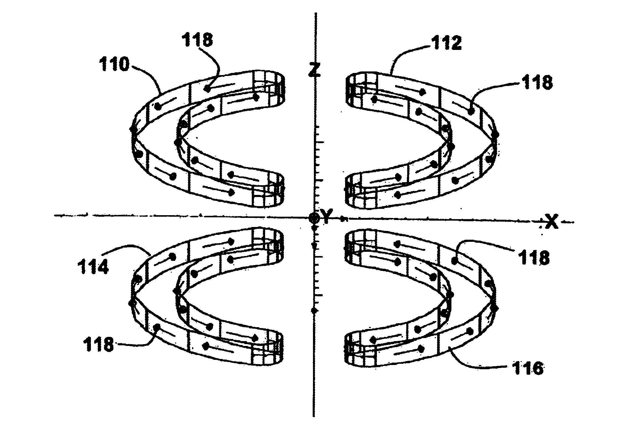
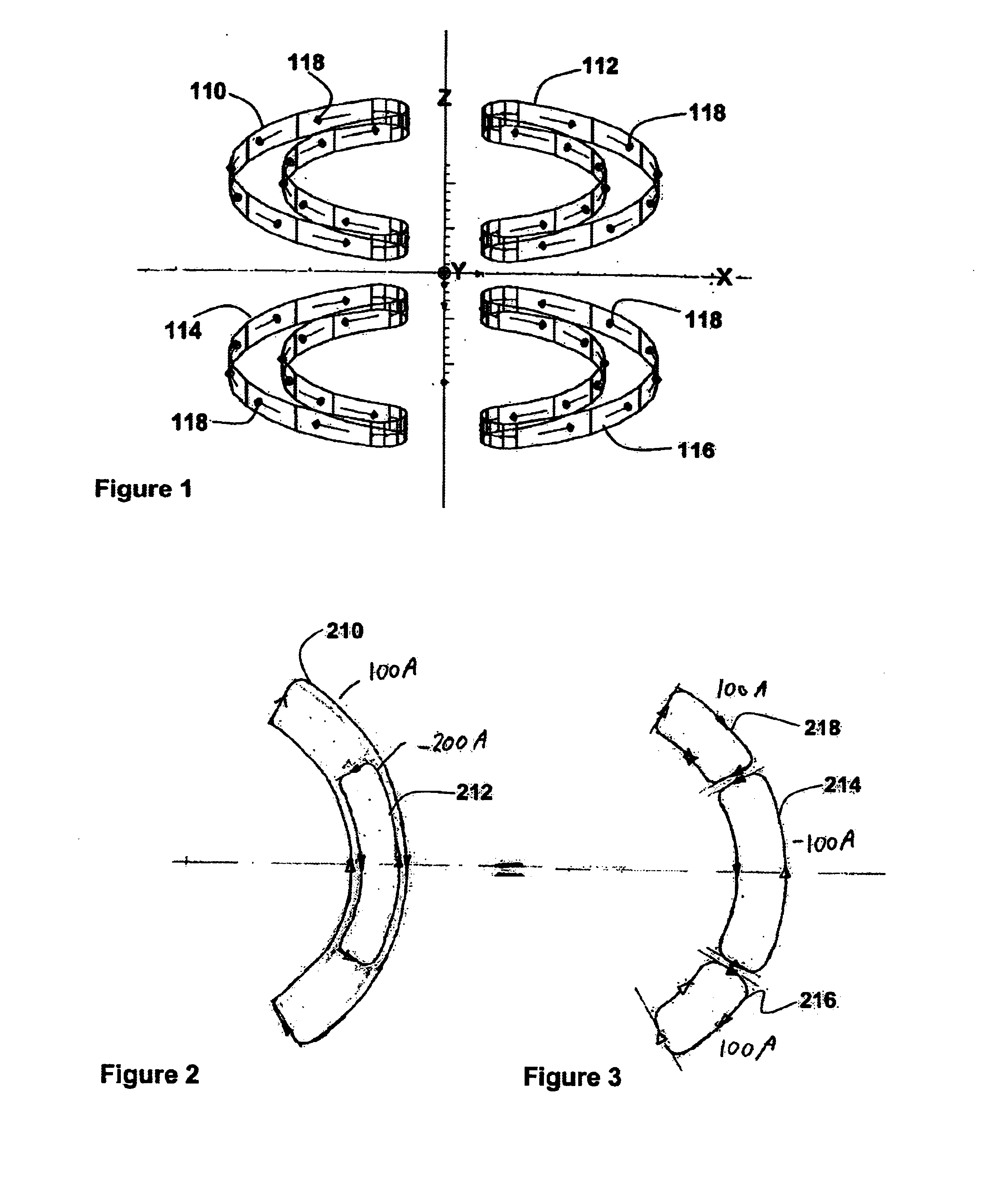
[0029]FIG. 1 shows an arrangement consisting of four coils 110, 112, 114, 116 and a XYZ coordinate reference frame, which will be referred to in the following description. The coils 110-116 shown in FIG. 1 are symmetrically arranged with respect to the X-Y plane, whi...


PUM

PropertyMeasurementUnit
diameteraaaaaaaaaa
magnetic fieldaaaaaaaaaa
lengthaaaaaaaaaa

Abstract

The present invention relates to magnets and to magnetic resonance imaging systems. The magnet is open with magnetic coils arranged in quadrant, separated about two perpendicular planes, a midplane and a plane of reflection, and wherein the windings are configured such that, in operation, current flow is symmetrical about the plane of reflection and anti-symmetrical about the midplane, to produce a nett magnetic field at the center in a direction perpendicular to the plane of reflection.

Description

FIELD OF THE INVENTION[0001]The present invention relates to magnets and, in particular but not necessarily so restricted, relates to magnets for magnetic resonance imaging equipment, especially to magnets which are open, i.e. magnets in which an imaging volume, wherein that portion of a patient being imaged is positioned, is not surrounded by the magnet.BACKGROUND OF THE INVENTION[0002]A special requirement for MRI is a strong uniform magnetic field, typically 0.2 to 2 Tesla, with a field homogeneity of a few parts per million in the imaging volume, typically a sphere of 30 cm to 50 cm in diameter. Most commonly such a field is produced by an electromagnet having a solenoid construction but this necessitates a patient being surrounded by the magnet and enclosed within a central bore tube. Although the length of this bore tube is typically 1.6 m or less it can cause a feeling of claustrophobia which is extremely distressing to some patients. Furthermore, such a design does not give ...

Claims


Application Information

Patent Timeline
Patent Type & Authority Patents(United States)
IPC IPC(8): G01R33/38G01R33/3815A61B5/055H01F6/00
CPCG01R33/3806G01R33/3815
Inventor KRUIP, MARCEL JAN MARIEBEASLEY, PAUL
Owner OXFORD MAGNET TECH LTD
Why Eureka
Try Eureka