Process and apparatus for producing a substrate having a coating resin layer

Inactive Publication Date: 2005-10-11
CANON KK
View PDF10 Cites 21 Cited by
  • Summary
  • Abstract
  • Description
  • Claims
  • Application Information

AI Technical Summary

Benefits of technology

[0040]The present invention has significant advantages which cannot be easily expected from the prior art. Particularly, for instance, in order to resin-seal a substrate having a photovoltaic element as a typical example of the substrate which is used outdoors, by making the fastening table and the conveying system to be smaller than said substrate as above described, when the resin layer precursor is applied on the substrate to coat the substrate, the fastening table and the conveying system are prevented from being stained with the resin layer precursor. Because of this, the maintenance frequency of the apparatus can be diminished, and the operating efficiency of the apparatus is improved.
[0041]In addition, because the fastening table and the conveying system are not strained as above described, there is not such an occasion that contaminants are transferred to the photovoltaic ele

Problems solved by technology

However, these solar cell production processes using such lamination apparatus have disadvantages such that a plurality of lamination materials are necessary to be used and a large investment in plant and equipment is required, and therefore, the resulting solar cell unavoidably becomes costly, and this results in a raise in the power generation cost of the solar cell.
However, an

Method used


Image

  • Process and apparatus for producing a substrate having a coating resin layer
  • Process and apparatus for producing a substrate having a coating resin layer
  • Process and apparatus for producing a substrate having a coating resin layer

Examples


Example

EXAMPLE 1

1. Preparation of Photovoltaic Element:

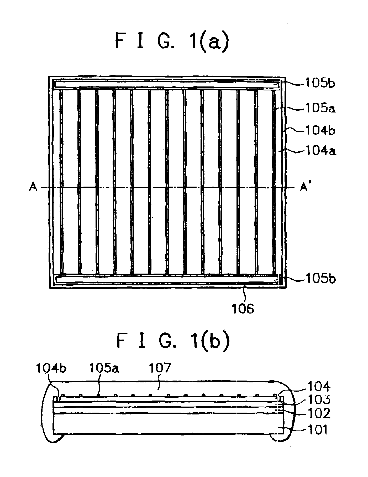
[0094]An amorphous silicon (a-Si) photovoltaic element having such configuration as shown in FIGS. 1(a) and 1(b) with no resin layer 107 was prepared in the following manner.

[0095]There was provided a well-cleaned stainless web substrate having a thickness of 150 μm and a width of 355 mm as the substrate 101. On the web substrate, there was formed a two-layered back reflecting layer 102 comprising a 5000 Å thick Al film / a 5000 Å thick ZnO film by means of the conventional roll-to-roll sputtering process.

[0096]On the back reflecting layer 102 thus formed, there was formed a tandem type photoelectric conversion semiconductor layer as the semiconductor active layer 103 comprising a 150 Å thick n-type amorphous silicon layer / a 4000 Å thick i-type amorphous silicon layer / a 100 Å thick p-type microcrystalline silicon layer / a 100 Å thick n-type amorphous silicon layer / a 800 Å thick i-type amorphous silicon layer / a 100 Å thick p-type microcrys...

Example

EXAMPLE 2

[0125]The procedures of Example 1 were repeated, except that a curtain coater was used as the spouting means and the spouting width of the resin layer precursor to get down on the surf ace of the photovoltaic element was made to be 300 mm, to obtain three photovoltaic elements having a resin-sealed structure.

[0126]The resultant three photovoltaic elements were evaluated in the same manner as in Example 1. The evaluated results are shown in Table 1.

Example

COMPARATIVE EXAMPLE 1

[0127]The procedures of Example 1 were repeated, except that the resin layer precursor was applied to the photovoltaic element in a state that the waste liquid pan was maintained at a position having a distance of 20 mm from the edge portions of the photovoltaic element without lifting the waste liquid pan, to obtain three photovoltaic elements having a resin-sealed structure.

[0128]The resultant three photovoltaic elements were evaluated in the same manner as in Example 1. The evaluated results are shown in Table 1.


PUM

PropertyMeasurementUnit
Viscosityaaaaaaaaaa
Sizeaaaaaaaaaa
Widthaaaaaaaaaa

Abstract

A process for producing a substrate having a coating resin layer includes the steps of carrying in a substrate on a fastening table and fastening the substrate to the table and, while moving a spout for spouting a resin layer precursor or the fastening table in a horizontal direction, spouting the resin layer precursor to apply the resin layer precursor onto the substrate to form a resin layer precursor layer on the substrate. Additional steps include carrying out the substrate having the resin layer precursor layer from the fastening table, and drying and curing the resin layer precursor layer on the substrate to form a coating resin layer on the substrate.

Description

BACKGROUND OF THE INVENTION[0001]1. Field of the Invention[0002]The present invention relates to a process and an apparatus for producing a substrate having a coating resin layer which excels in weather resistance and durability and which also excels in productivity.[0003]2. Related Background Art[0004]In the case where a substrate such as a plastic plate, a steel plate or a galvanized steel plate is used outdoors, there is often adopted such a manner that prior to using said substrate decorative coating is performed so that the substrate has improved weather resistance and improved durability. In this case, for instance, when the substrate is a steel plate or a galvanized steel plate, it is important that a coating material which is satisfactory in terms of the weather resistance and the durability is used for the decorative coating and the interface between the coat layer and the steel plate or the galvanized steel plate is sufficiently covered and protected. As specific examples ...

Claims


Application Information

Patent Timeline
IPC IPC(8): B05C13/02B05C5/00B05C11/10B05D7/00B05D1/30B05D1/26B05D3/00B05D1/00B05D3/02B05D5/12B05D1/02H01L31/04H01L31/0203
CPCH01L31/0203
Inventor SHIOTSUKA, HIDENORITAKABAYASHI, AKIHARUKATAOKA, ICHIRO
Owner CANON KK
Why Eureka
Try Eureka