Positioning apparatus

a technology of positioning apparatus and positioning chamber, which is applied in the direction of machines/engines, instruments, printing machines, etc., can solve the problems of inability to achieve good processing accuracy, minute deformation of the casing, and contamination of the inside of the process chamber with lubricant supplied to a moving part thereo

Active Publication Date: 2005-10-11
NSK LTD
View PDF3 Cites 8 Cited by
  • Summary
  • Abstract
  • Description
  • Claims
  • Application Information

AI Technical Summary

Benefits of technology

[0008]It is an object of the invention is to provide a positioning apparatus operable to circumvent or alleviate an influence of the trouble caused in an exhaust system.

Problems solved by technology

In the case that a positioning apparatus is provided in the process chamber, there is a fear that lubricant supplied to a moving part thereof may scatter and contaminate the inside of the process chamber.
However, for instance, when the process chamber is vacuumized, a large force due to the difference in pressure between the inside and the outside of the casing is applied to a casing covering the process chamber, so that minute deformation of the casing occurs.
Thus, there is a fear that processing cannot be achieved with good accuracy.
However, the increase in the thickness of the moving block causes a new problem in that the entire system gets heavy.
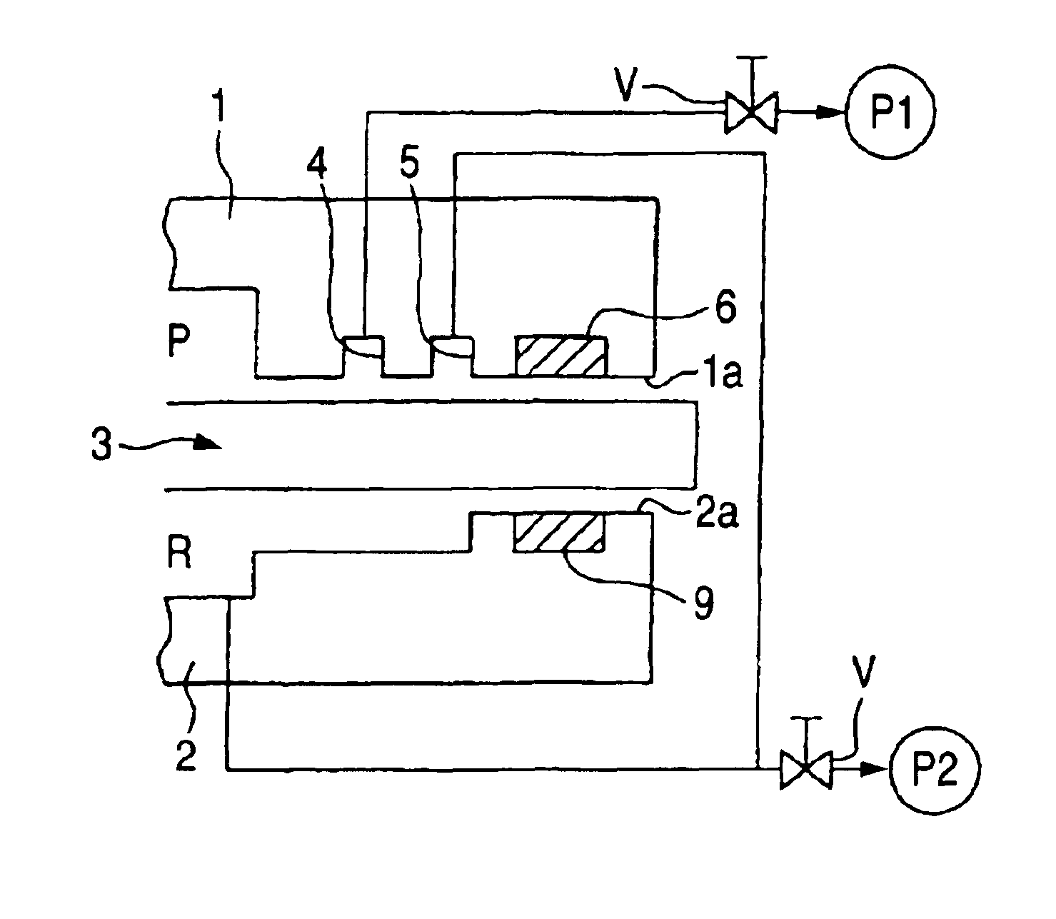
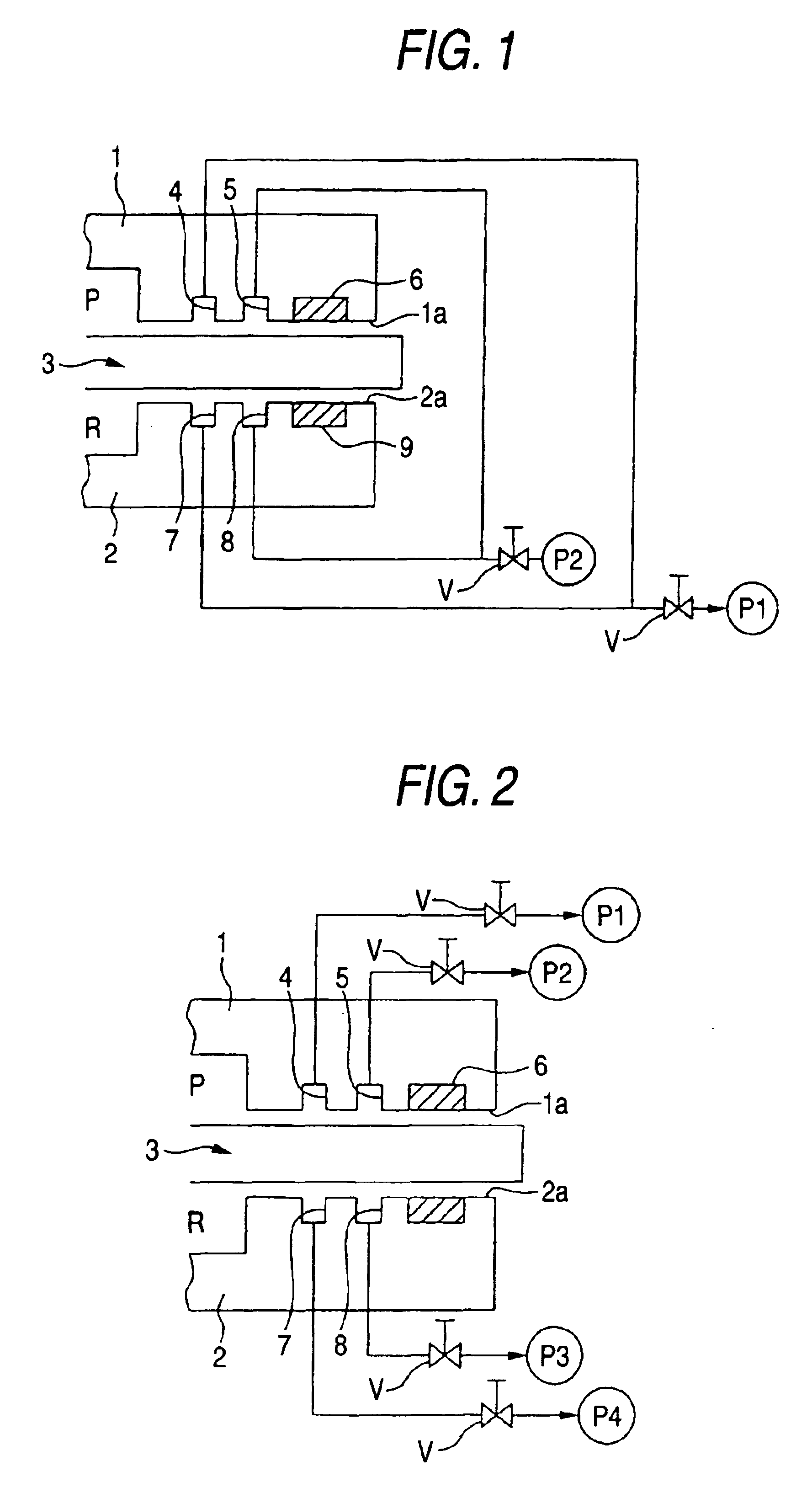
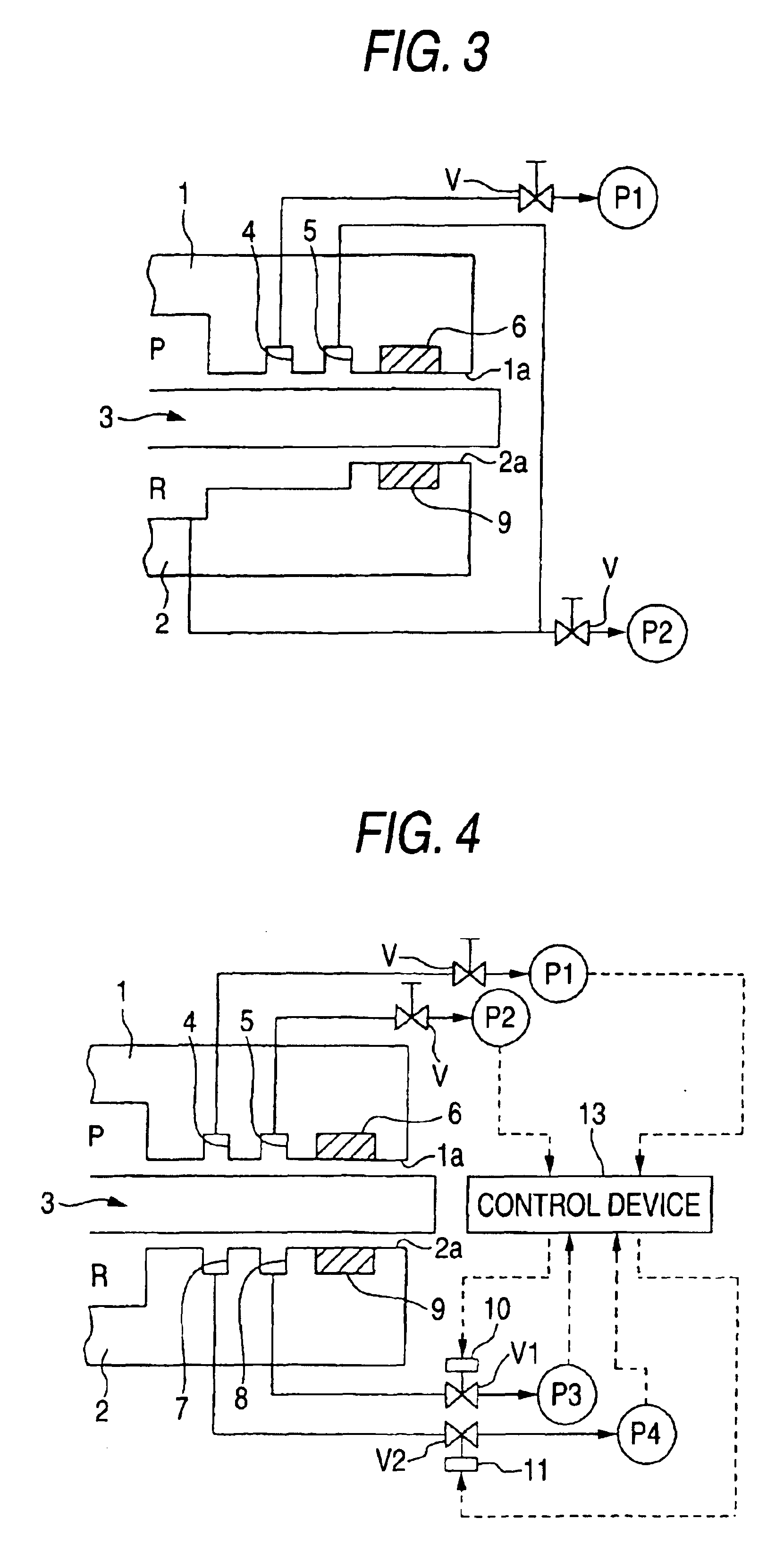
However, in such a configuration of the system, it is necessary to provide differential pumping seals at both the side of the process chamber and the side of the decompression chamber.
Nevertheless, when some trouble occurs at in an exhaust pump for causing the differential pumping seals to operate, and in piping thereof, atmospheric air enters the process chamber P, so that the barometric pressure therein increases.
Further, there is a fear that an object being processed may become a defective product.

Method used


Image

  • Positioning apparatus
  • Positioning apparatus
  • Positioning apparatus

Examples


first embodiment

[0073]Hereinafter, preferred embodiments of the invention are described with reference to the accompanying drawings. FIG. 5 is a front sectional view of a positioning apparatus 110 according to the invention, and shows this embodiment by omitting an upper part of sealed casing and simplifying the differential pumping seal and the hydrostatic bearing. FIG. 6 is a sectional view of the positioning apparatus 110 taken on line VI—VI of FIG. 5 in the direction of arrows. FIG. 7 is a sectional view of the positioning apparatus 110 taken on line VII—VII of FIG. 6 in the direction of arrows. Each of FIGS. 8 to 10 is a sectional view of the positioning apparatus 110 taken on an associated one of lines VIII—VIII, IX—IX, and X—X of FIG. 6 in the direction of arrows.

[0074]As illustrated in FIG. 5, the positioning apparatus 110 according to this embodiment has a first casing 120, which contains a process chamber P and has an opening 120a linking the process chamber P with the outside thereof, a ...

second embodiment

[0093]Further, the valve V2 and the actuator 191 are associated with the exhaust pump P2 for exhausting air in the decompression chamber R. Moreover, only the exhaustion of air from the decompression chamber R is stopped by the valve V2 and the actuator 141. In addition to the aforementioned case, each of the aforementioned control device can be used for temporarily reducing the gap between the moving block 3 and the intermediate block 170, alternatively, for bringing both the moving block 3 and the intermediate block 170 into intimate contact with each other. Incidentally, in the second embodiment, similarly as the valves V and V1, a valve adapted to perform only switching between ON and OFF (that is, opened and closed states) is employed as the valve V2 provided at the position at which only an operation of sucking the labyrinth seal 160 is interrupted. Instead of this valve, a valve, such as a needle valve, enabled to perform pressure control operations (that is, flow rate contro...

third embodiment

[0098]Although not shown, an example of modification of the aforementioned embodiment is adapted when an operation of sucking the inner differential pressure chamber of the inside of the differential pumping seal 150 provided at the side of the process chamber P is performed by a first exhaust pump, when an operation of sucking the outer differential pressure chamber of the differential pumping seal 150 provided at the side of an external portion is performed by a second exhaust pump, when an operation of sucking the differential pumping seal 160 is performed by a third exhaust pump, and even though the valve V1 is formed at a position where only an operation of sucking the differential pumping seal 160 by the third exhaust pump is interrupted in case that the valve V1 is driven and closed by the actuator 190. This modification also operates similar to the Incidentally, it is optional to combine this example of modification with each of the aforementioned embodiments. Further, alth...


PUM


Abstract

In case that some trouble occurs in exhaust pump or in pipe, internal pressure of groove comes closer to atmospheric pressure owing to leak-in of air, because the groove adjoins groove opened to atmospheric air. However, the internal pressures of grooves are maintained at negative value. Thus, difference in pressure between the top and bottom surfaces of moving block is generated. Further, the gap between the moving block and the intermediate block decreases. Consequently, the deterioration in the degree of vacuum in the process chamber can be retarded. During retarded time, measures to protect an object to be processed, such as operation of tightly sealing the object can be taken. Further, in case that the system recovers, time required to operate turbo-molecular pump for sucking the inside of the process chamber is reduced to a short time. Therefore, the processing can be quickly resumed.

Description

BACKGROUND OF THE INVENTION[0001]1. Field of the Invention[0002]The present invention relates to a positioning apparatus enabled to move a work in, for example, a chamber isolated from external environment.[0003]2. Description of the Related Art[0004]In a semiconductor manufacturing apparatus, a work is processed by being put on a stage and moved in a process chamber, the inside of which is maintained in a vacuum state or in a special gaseous atmospheric state. In the case that a positioning apparatus is provided in the process chamber, there is a fear that lubricant supplied to a moving part thereof may scatter and contaminate the inside of the process chamber.[0005]To solve such a problem, for example, U.S. Pat. No. 4,191,385 discloses an integral negative-pressure-sealed gas-bearing assembly. According to such related art techniques, a moving part enabled to move in two-dimensional directions is provided on a bearing block. Further, a process chamber is formed between the bearing...

Claims


Application Information

Patent Timeline
Patent Type & Authority Patents(United States)
IPC IPC(8): H01L21/67H01L21/68H01L21/00F16C32/06F16C32/00
CPCF16C29/025F16C33/748H01L21/67126H01L21/68F16C32/0614F16C2300/62F16C32/0618
Inventor NAKAMURA, TSUYOSHISAJI, NOBUHITO
Owner NSK LTD
Why Eureka
Try Eureka