FET band amplifier

a band amplifier and fet technology, applied in the direction of amplifiers with semiconductor devices/discharge tubes, differential amplifiers, amplifiers with semiconductor devices only, etc., can solve the problem of inability to obtain a gain realizable in design, and achieve the effect of reducing the 1/f noise generated in the fet, and less to reducing the overall low-frequency nois

Inactive Publication Date: 2005-10-11
RICOH KK
View PDF13 Cites 3 Cited by
  • Summary
  • Abstract
  • Description
  • Claims
  • Application Information

AI Technical Summary

Benefits of technology

[0006]The present invention has been created in consideration of the above-described points, and an object of the present invention is to provide an FET band amplifier which can obtain a high gain.
[0007]In order to solve the above-mentioned problem, an FET band amplifier of the present invention is provided in amplifiers cascaded in a plurality of stages in which FETs are used as amplifier elements and a band-pass filter inserted in mid-stage of these amplifiers of multiple stages and adjusted to have a passing band wider than an amplification band. Furthermore, p-channel FETs are used as FETs of at least first to nth-stage amplifiers. It is possible, by using the band-pass filter having a passing band wider than the amplification band, to eliminate 1 / f noise existing on a lower-frequency side than the passing band and thermal noise existing on a higher-frequency side than that. Furthermore, a noise occurring in the amplifier can be further reduced by using as an amplification element a p-channel FET having a small mobility. Therefore, it is possible to prevent the amplifiers from being saturated with such noise component, and only a signal component to be originally amplified can be amplified so that a high gain can be obtained as the entire FET band amplifier. Furthermore, by using an FET as an amplification element, the entire FET band amplifier can be fabricated on a semiconductor substrate in a process for producing FETs, thus making it possible to make an integration process easier and achieve a reduction of costs and savings in space, compared to the case where a bipolar transistor is used as an amplification element.
[0008]Particularly, the above amplifier is a differential amplifier that differentially operates two FETs, and where the number of stages in which noise components are accumulated so that the amplifier becomes saturated is m, it is desirable that the band-pass filter is placed after amplifiers cascaded in a number smaller than m. Since the band-pass filter is inserted so that the number of cascaded stages is smaller than m, the amplifiers after the mth stage can be prevented from being saturated by noise components, thus making it possible to increase the gain of the entire FET band amplifier.

Problems solved by technology

Incidentally, the band amplifier described above has a problem such that if a high gain is set, the multistage amplifier may be saturated with the noise component, thus making it impossible to obtain a gain realizable in design.

Method used


Image

  • FET band amplifier
  • FET band amplifier
  • FET band amplifier

Examples


first embodiment

[First Embodiment]

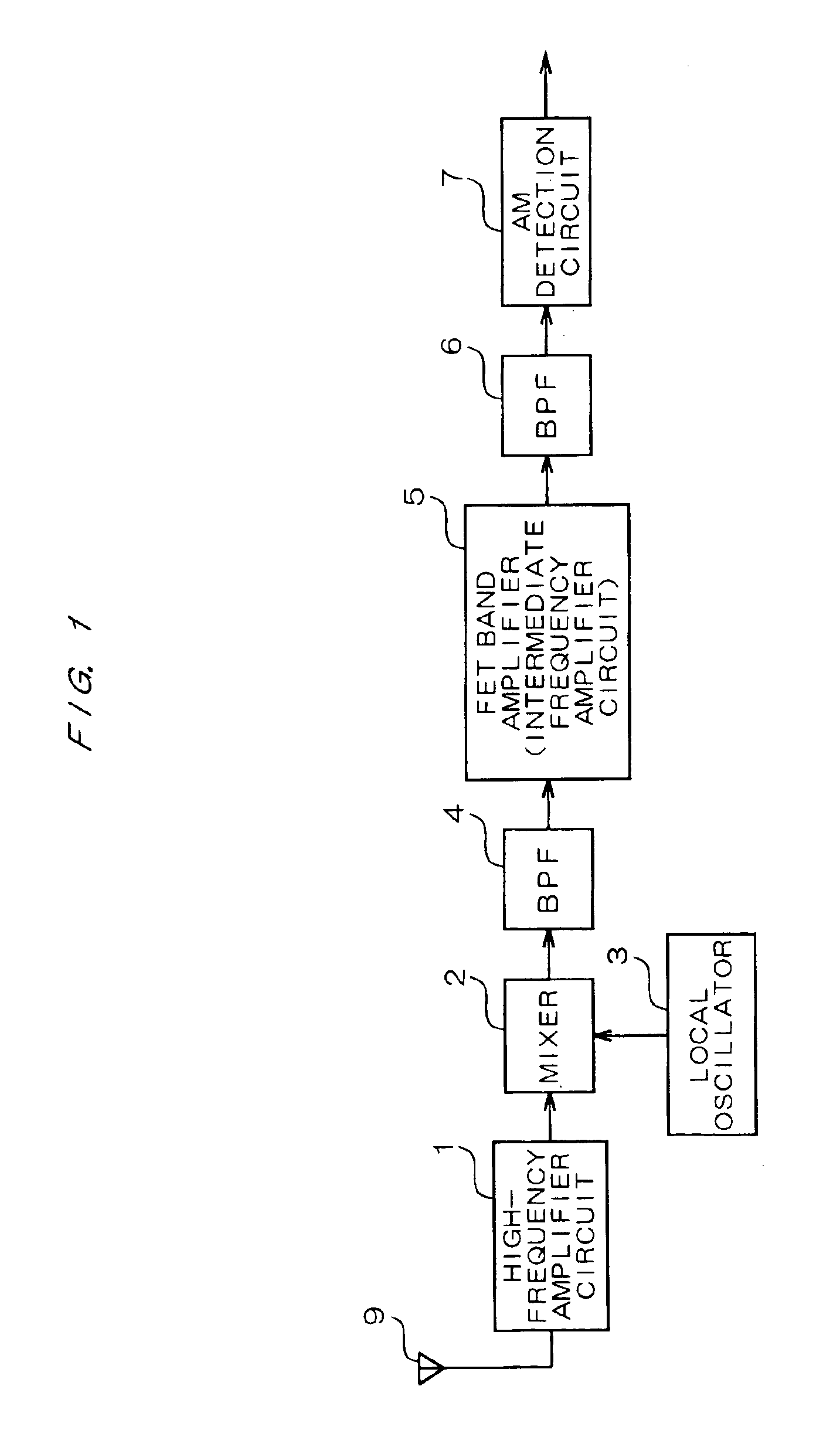
[0036]FIG. 1 is a diagram showing a general configuration of an AM receiver including the FET band amplifier according to a first embodiment. As shown in FIG. 1, the AM receiver has a high-frequency amplifier circuit 1, a mixer 2, a local oscillator 3, BPF (Band-pass Filter) 4 and BPF 6, an FET band amplifier 5 and an AM detection circuit 7. An AM wave received by an antenna 9 is amplified by a high-frequency amplifier circuit 1 and then a local oscillation signal outputted from a local oscillator 3 is mixed so as to perform a frequency conversion from a high-frequency signal to an intermediate frequency signal. For instance, if a frequency of a signal outputted from the high-frequency amplifier circuit 1 is f1 and the frequency of the local oscillation signal outputted from the local oscillator 3 is f2, a signal having the frequency of f1-f2 is outputted from a mixer 2.

[0037]BPFs 4 and 6 are provided in foregoing and subsequent stages of an FET band amplifier 5 fu...

second embodiment

[Second Embodiment]

[0054]One BPF is inserted after the third-stage amplifier 13 to remove noise components in the first embodiment described above, but noise components may be removed in the amplifier of each stage.

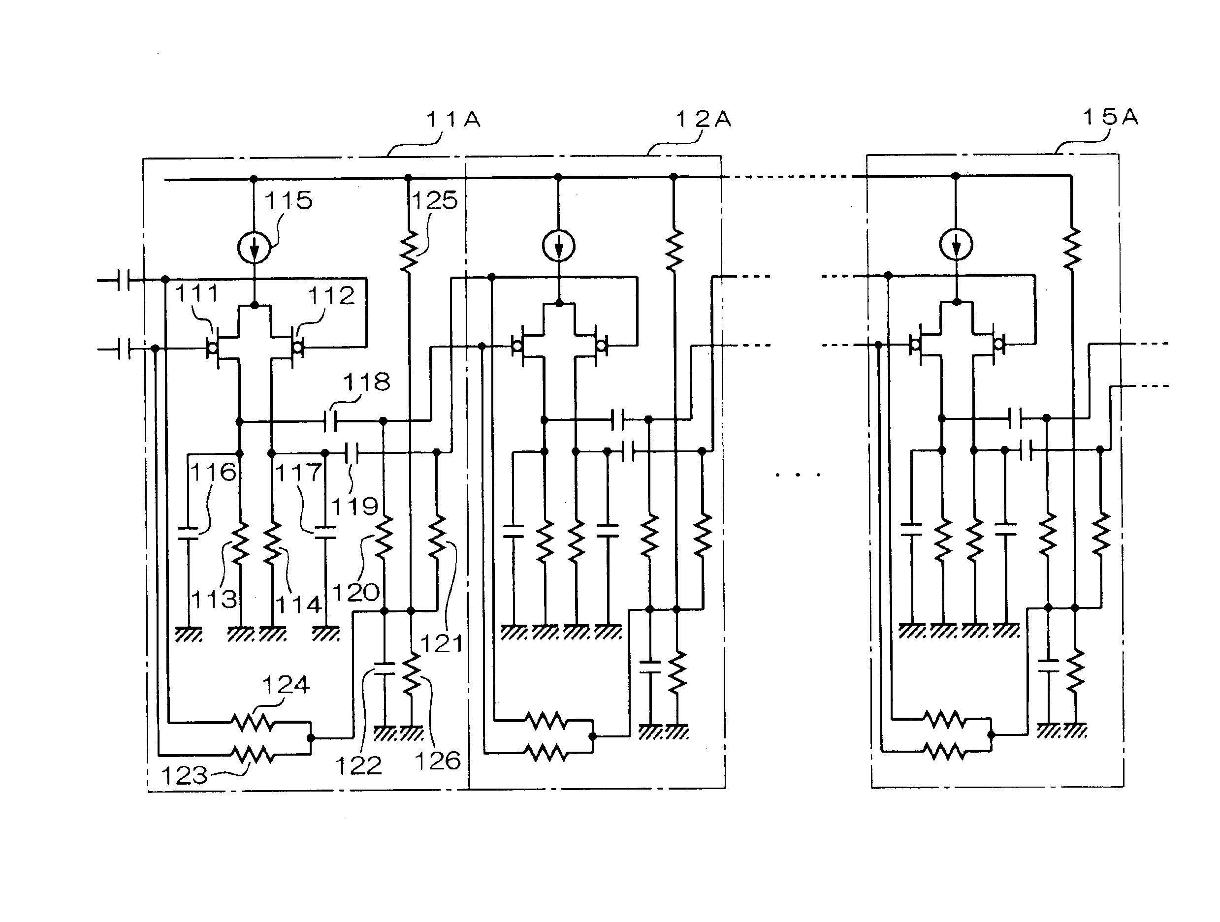
[0055]FIG. 4 is a circuit diagram showing the configuration of the FET band amplifier according to a second embodiment. The FET band amplifier according to this embodiment shown in FIG. 4 is constituted by cascading the amplifiers in five stages 11A, 12A, . . . 15A. As the configurations of these amplifiers are basically the same, the detailed configuration and operation will be described hereafter by paying attention to the first-stage amplifier 11A.

[0056]The amplifier 11A is comprised of two p-channel MOS FETs 111, 112, eight resistors 113, 114, 120, 121, 123, 124, 125 and 126, a constant current circuit 115 and five capacitors 116 to 119 and 122. Of these, the FETs 111, 112, the resistors 113, 114 and the constant current circuit 115 are in common with the configuratio...

third embodiment

[Third Embodiment]

[0070]FIG. 6 is a circuit diagram showing the configuration of the FET band amplifier according to a third embodiment. The FET band amplifier according to this embodiment shown in FIG. 6 includes the amplifiers cascaded in five stages 11C, 12C, . . . 15C and an additional circuit for taking out the signal outputted from the final-stage amplifier 15C and feeding it back to the first-stage amplifier 11C.

[0071]As the configuration of each of the amplifiers 11C to 15C is the same, a description will be given hereafter by paying attention to the first-stage amplifier 11C.

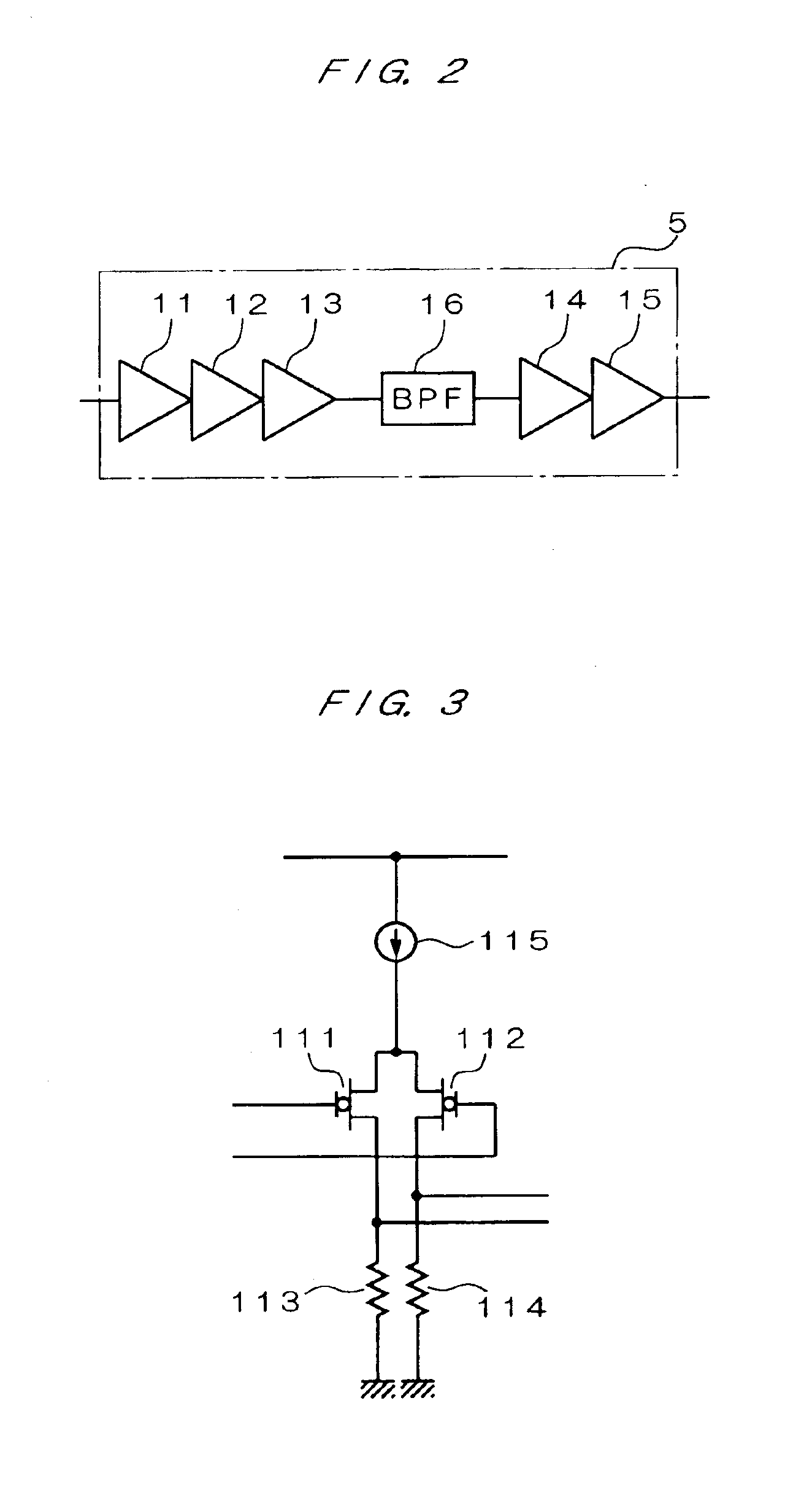
[0072]The amplifier 11C is comprised of the FETs 111a, 112a, resistors 113, 114 and constant current circuit 115. The amplifier 11C has the configuration which is basically the same as the amplifier 11 shown in FIG. 3. However, the p-channel MOS FETs 111a, 112a shown in FIG. 5 are used instead of the FETs 111, 112. To be more specific, the FETs 111a, 112a have the gate length L and the gate width W set ...


PUM


Abstract

An FET band amplifier for providing a high gain. An FET band amplifier 5 included in an AM receiver comprises amplifiers 11 to 15 e.g. at five stages and a BPF 16 inserted halfway in their connection. Each of the amplifiers 11 to 15 acts as a differential amplifier comprising a p-channel FET as an amplification element. The BPF 16 allows the passage of a component of a band wider than the amplification band of the whole of the FET band amplifier and reduces a 1 / f noise by removing the low-band component of a signal amplified by the amplifiers 11 to 13 at three stages and thermal noise by removing the high-band component. Thus, each of the amplifiers 14, 15 connected to the rear stage of the BPF 16 is not saturated by a noise component.

Description

BACKGROUND OF THE INVENTION[0001]1. Field of the Invention[0002]The present invention relates to an FET band amplifier used in various receivers and so on.[0003]2. Description of the Related Art[0004]Band amplifiers that amplify signals of a predetermined band in high gain are used in various kinds of receivers such as an AM receiver and an FM receiver. Typical band amplifiers include a high-frequency amplifier included in a front end and an intermediate frequency amplifier that amplifies intermediate frequency signals. In the high-frequency amplifier, only signals of in a predetermined band centering around a tuning frequency are selectively amplified. The center frequency in this case is set to be variable depending on the state of channel selection. In the intermediate frequency amplifier, only signals of a narrow band close to the intermediate frequency are selectively amplified. The center frequency in this case is set to a fixed value such that for example, the center frequenc...

Claims


Application Information

Patent Timeline
Patent Type & Authority Patents(United States)
IPC IPC(8): H03F3/16H03F3/45H03F3/189H03F3/04H03F3/193H03F3/195
CPCH03F3/16H03F3/193H03F3/195H03F3/45645H03F2200/168H03F2200/54H03F2203/45051H03F2203/45458H03F2203/45526H03F2203/45631H03F2203/45652
Inventor MIYAGI, HIROSHI
Owner RICOH KK
Why Eureka
Try Eureka