
Capacitive sensing employing a repeatable offset charge

a technology of offset charge and capacitor, applied in the field of capacitive sensing, can solve the problems of increasing the demand for longer intervals between battery replacement or recharging, increasing the time and energy consumption of such devices, and affecting so as to reduce time and energy, improve the reliability of detection, and effective power management

Inactive Publication Date: 2005-10-11
MICROSOFT TECH LICENSING LLC
View PDF101 Cites 37 Cited by
  • Summary
  • Abstract
  • Description
  • Claims
  • Application Information

AI Technical Summary

Benefits of technology

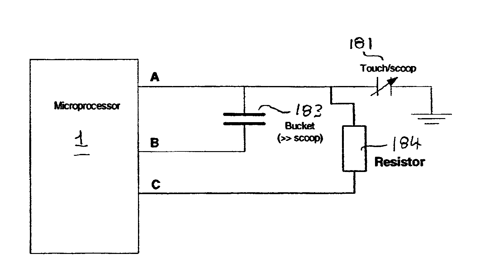
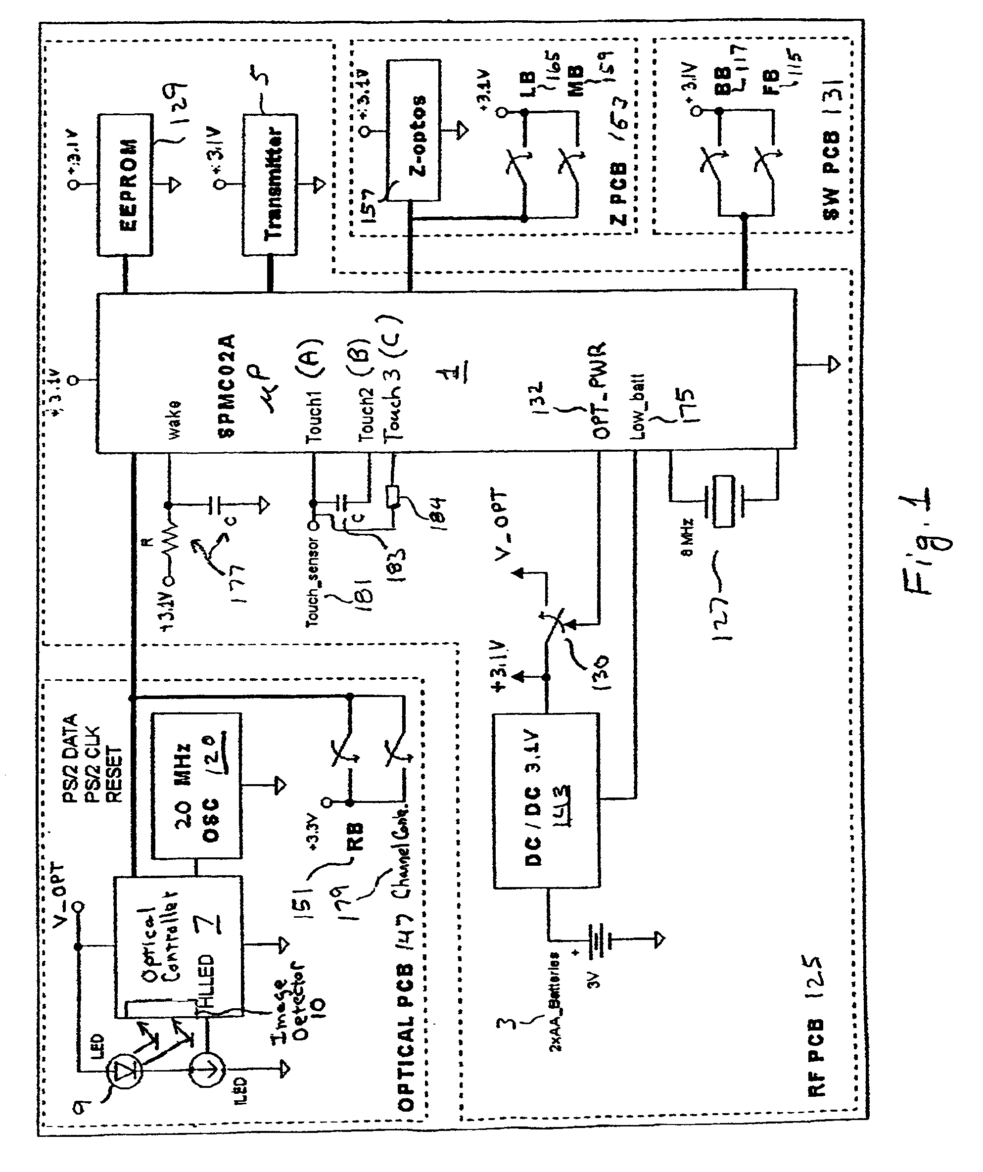
[0016]In view of the foregoing, the present invention has as an object to reduce the time and energy required to successfully detect the presence of a human hand or other instrumentality in contact or close proximity with a data input device, e.g., a computer mouse, while improving the reliability of the detection. The capacitive sensing systems and methods of the invention may be advantageously utilized to provide effective power management in user operated data input devices. The invention is not limited to power management, however, and can be implemented in essentially any application (data input devices or otherwise) where there is a desire to reliably and efficiently sense the presence (or absence) of an object or body portion in contact with or close proximity to another object. Particularly advantageous use may be made of the inventive capacitive sensing together with power management systems and methods as described in copending commonly owned U.S. application Ser. No. 09 / 948,099, to substantially increase battery life in a wireless cursor control device (e.g., computer mouse or trackball device) or other user operated data input device, e.g., a wireless gaming peripheral such as a gamepad, or a handheld digitizing pen, especially one including circuit components (e.g., an optical tracking system and / or RF transmitter) that draw relatively large amounts of electrical power.

Problems solved by technology

The components of such devices are becoming increasingly power hungry, and the demand for longer intervals between battery replacement or recharging has increased.
Such devices are often turned on for ready usability but left idle for significant periods of time.
Without effective power management, continuous operation of such wireless peripherals will rapidly deplete the limited battery power of the device, thus requiring frequent battery replacement or recharging.
Heretofore, limited use of optical tracking systems has been made in wireless cursor control devices, due to the relatively large power requirements of both the optical tracking system and the wireless data transmitter.
The determination of this condition requires periodic sequences of microprocessor operation, causing increased current draw during the detection interval.
When capacitive sensing techniques, e.g., as described in application Ser. No. 09 / 948,099, are used to detect operator interaction, however, aggressive users, e.g., gamers utilizing a mouse or other gaming peripheral (e.g., a gamepad), may move fast enough to notice a lack of responsiveness, due to the interval delay required to successfully detect a hand actuation.
Sampling at a higher rate can alleviate perceived deficiencies in responsiveness, but increased sampling adversely affects battery life.
The use of battery power for optical tracking in computer mice and other data input devices presents a significant challenge from a power management perspective.
Known optical tracking engines requires substantial current from the limited battery source.
Additionally, the time and energy that it takes to detect hand presence limit the periodicity (frequency) with which detection sampling might take place.

Method used


Image

  • Capacitive sensing employing a repeatable offset charge
  • Capacitive sensing employing a repeatable offset charge
  • Capacitive sensing employing a repeatable offset charge

Examples


Embodiment Construction

[0028]The present inventive systems and methods are described herein in terms of an exemplary application thereof within a computer input device, particularly a wireless, optically tracking computer mouse. It will be understood, however, that the inventions have much wider-ranging potential application. The capacitive sensing of the present invention is not limited to power management, but rather can be implemented in virtually any device (data input device or otherwise) where it is desired to determine the presence or non-presence of an object or body portion in contact with or close proximity to another object. This includes many applications where various other types of proximity sensors have been used, e.g., water valve actuation in toilets, faucets and drinking fountains, automatic door control systems, alarm systems, security lock systems and safety interlock systems (e.g., for industrial equipment), etc.

[0029]It will be understood that the phrase “contact with or close proxim...


PUM


Abstract

Capacitive proximity sensing is carried out by detecting a relative change in the capacitance of a “scoop” capacitor formed by a conductor and a surrounding ground plane. Charge is transferred between the “scoop” capacitor and a relatively large “bucket” capacitor, and a voltage of the bucket capacitor is applied to an input threshold switch. A state transition (e.g., from low to high, or high to low) of the input threshold switch is detected and a value (TouchVal) indicative of a number of cycles of charge transfer required to reach the state transition is determined. The presence or absence of an object or body portion in close proximity to or contact with a device can be determined by comparing TouchVal with a predetermined threshold value (TouchOff). In order to lessen the time required for detection, and / or improve the sensitivity thereof, the bucket capacitor may initially be charged to a repeatable non-zero reference level closer to the charge level that will cause a state transition. TouchOff can be adjusted to take into account environmentally induced (non-touch related) changes in the capacitance of the scoop capacitor. Power management may be provided in a user operated data input device utilizing the inventive proximity sensing.

Description

FIELD OF THE INVENTION[0001]The present invention relates to sensing systems and methods that may be advantageously used in managing power consumption in electronic devices, particularly hand operated data input devices, and for other purposes. More specifically, the invention relates to sensing systems and methods that may be used to conserve battery power in wireless data input devices having components that consume power at a relatively high rate.BACKGROUND OF THE INVENTION[0002]Power management in electronic devices is becoming increasingly important as greater reliance is placed on battery power, e.g., for portable computers, personal data assistants (PDAs), tablet computers, cellular phones, pagers, and wireless computer peripherals. The components of such devices are becoming increasingly power hungry, and the demand for longer intervals between battery replacement or recharging has increased. Such devices are often turned on for ready usability but left idle for significant ...

Claims


Application Information

Patent Timeline
IPC IPC(8): G06F1/32G06F3/033G01V3/08G06F3/0354
CPCG06F1/3203G06F1/3231G06F3/03543Y02B60/1289Y02D10/00
Inventor CASEBOLT, MARK W.RENSBERGER, GARYBATHICHE, STEVEN N.ALBULET, MIHAI
Owner MICROSOFT TECH LICENSING LLC
Learn More