Method for secondary oil recovery

a technology for oil recovery and secondary oil, applied in the direction of filtration separation, separation process, borehole/well accessories, etc., can solve the problems of inability to operate in warm or tropical regions, too experienced significant limitations, etc., and achieve effective and efficient operation, enhance the transmission of chloride ions into the permeate, and improve the effect of oil recovery

Inactive Publication Date: 2005-10-18
GE OSMONICS INC
View PDF10 Cites 23 Cited by
  • Summary
  • Abstract
  • Description
  • Claims
  • Application Information

AI Technical Summary

Benefits of technology

[0008]Applicant has provided an enhanced method of secondary oil recovery, particularly relating to offshore oil operations. In Applicant's improved method, ambient temperature seawater including warm seawater from tropical regions, as well as seawater that might be raised in temperature as a result of energy absorbed during pumping, which seawater may contain a fairly high chloride ion content, can be directly treated without temperature regulation and then injected into a subterranean hydrocarbon-bearing formation by a single step treatment with a spirally-wound separation unit comprising sheets of semipermeable membrane material and feed spacer material. Preferably, the membrane is a polyamide nanofiltration membrane formed by interfacial condensation of piperazine and an aromatic triacyl chloride, e.g. TMC, or a mixture of TMC and IPC, upon an ultrathin polyurethane film, which is in turn supported on a standard porous support sheet material made of polysulfone or the like; more preferably, the membrane is of the type sold by Osmonics / Desal as their nanofiltration membrane DS-5. The membrane in sheet form is spirally wound in cartridges with feed spacer material that provides parallel ribs which form about 3 to 10 axially extending channels per inch, which ribs are interconnected by transverse filaments; this arrangement provides concentration-polarization-enhancing effects at the surface of the polyamide membranes which keeps calcium sulfate and minute solids from precipitating and enhances the transmission of chloride ion into the permeate. The overall characteristics of the system permit effective and efficient operation with saline water at a temperature between about 2° C. and 75° C. or even higher. As a result, treatment can be carried out of warm or even tropical saline water directly in a one-step operation without precooling or without the use of preliminary ultrafiltration or chemical treatment.
[0010]In a further more particular aspect, the invention provides a seawater treatment system for providing a divalent anion-reduced and chloride ion-enhanced aqueous feed for flooding a permeable petroleum-bearing stratum for the secondary recovery of petroleum from a location below the ocean or other body of water, which system comprises a spirally-wound cartridge containing sheets of semipermeable membrane and feed spacers having an axially extending parallel channel configuration that creates feed passageways in such spiral cartridge which negate membrane fouling from suspended solids and precipitation and thus obviate the need for any ultrafiltration prefiltering of seawater, and means for pumping seawater being treated to said membrane at a pressure of not greater than about 300 psig, said membrane being a polyamide continuous film formed from the condensation reactor of a piperazine and an acyl chloride, which film is supported upon a porous film of a different polymeric material, which is in turn supported upon a porous support of polysulfone or the like.

Problems solved by technology

Although the process taught in the '603 patent was worthwhile in reducing two RO treatment-steps to one membrane treatment step, it too experienced significant limitations.
It was often unable to achieve desired concentrations in a single step, and it was not able to operate in warm or tropical regions (where the temperature of the water being treated is substantially higher than that found in the North sea and other drilling locations where offshore oil production was occurring) without expensive cooling of the feedwater.

Method used


Image

  • Method for secondary oil recovery
  • Method for secondary oil recovery
  • Method for secondary oil recovery

Examples


Embodiment Construction

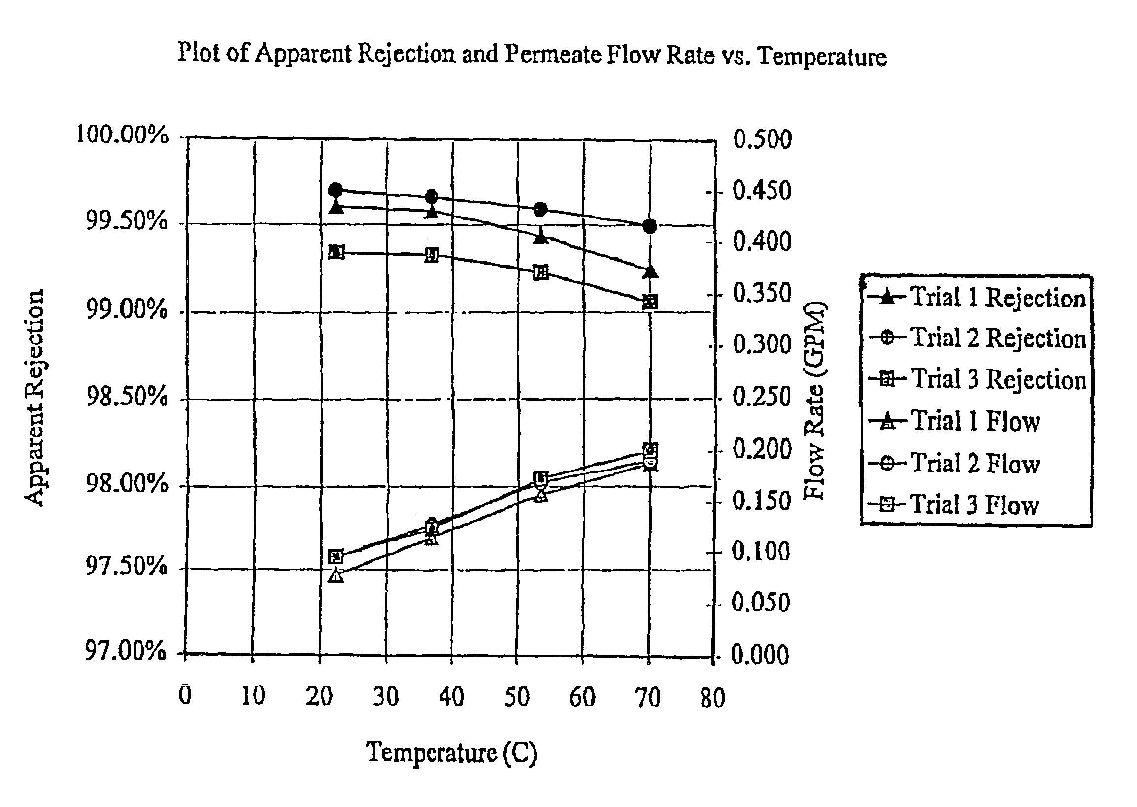
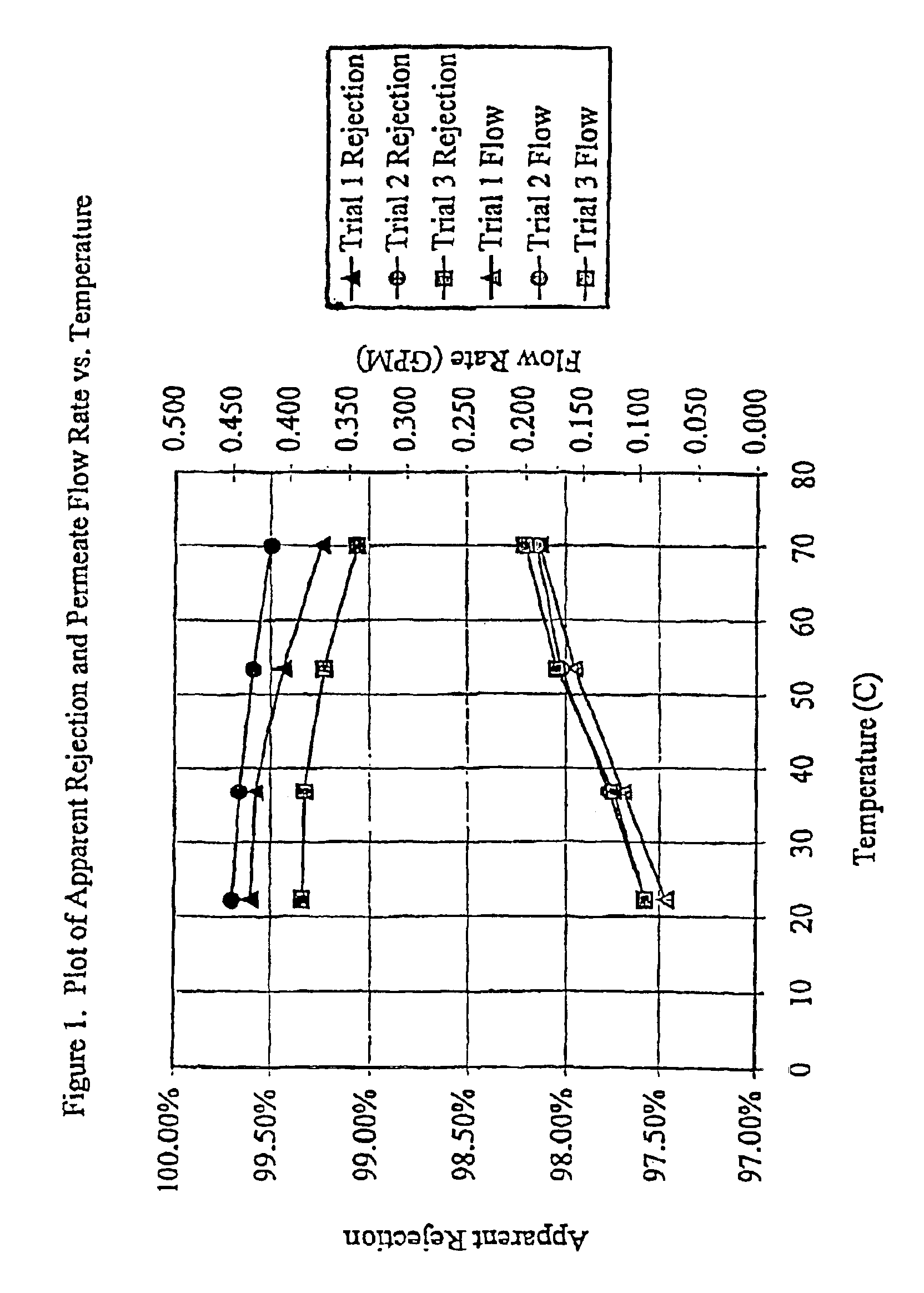
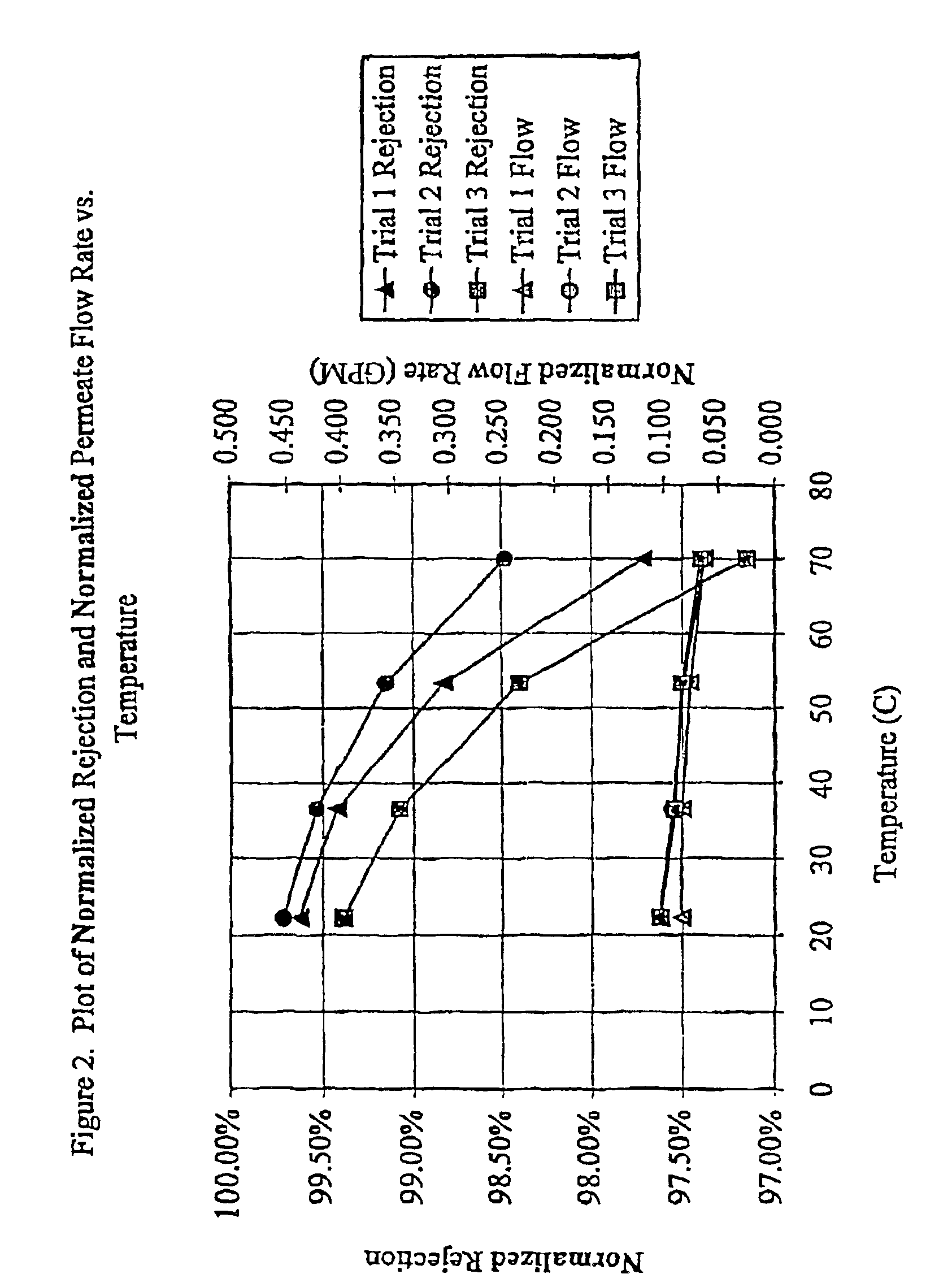
[0011]Applicant's improved method for secondary recovery of petroleum from a location below a body of saline water by flooding the permeable petroleum-bearing stratum utilizes a three-layer separation membrane in combination with a particular feed spacer arrangement which is capable of operation under conditions of relatively high ambient temperature and in the presence of some suspended solids in a spirally-wound membrane cartridge to produce a permeate that is substantially free of divalent ions but which contains desired high levels of monovalent ions, i.e. chlorides. This method facilitates the transformation in a single treatment step of source water, e.g. tropical seawater, into a liquid having such characteristics that it can be pumped directly into the permeable stratum to effect the desired flooding and secondary oil recovery. Moreover, operation can be carried out under a fairly broad range of pH conditions so as to facilitate appropriate periodic cleaning of such cartridg...


PUM


Abstract

A method and a system for treating seawater to facilitate secondary recovery of petroleum from a location below a body of saline water by flooding a permeable stratum with the treated water. The system utilizes a spirally-wound cross flow semipermeable membrane cartridge incorporating a three layer membrane arrangement preferably having nanofiltration characteristics which facilitates treatment of open ocean water by a single pass without any chemical or mechanical pretreatment to result in a liquid stream of desired character that can have greater ionic strength than the input seawater, e.g. at least about 18,000 ppm of chloride ion and less than 50 ppm of sulfate ion. This surprising objective is obtained even at high operating temperatures, e.g. as high as about 70° C., through the combination of the construction of the feed spacer and the nanofiltration character of the three layer membrane arrangement.

Description

[0001]This application claims priority from Brazilian application PI0003677-3, filed Aug. 7, 2000 and is a 371 filing of PCT / US01 / 41595, filed Aug. 7, 2001.[0002]This invention relates to a method for oil recovery as a part of enhanced oil production operations, and more particularly relates to a method for secondary oil recovery at a location below a saline body of water and a system for carrying out such a method.BACKGROUND OF THE INVENTION[0003]Offshore oil production normally involves secondary oil recovery for economical overall production; however, before an oil formation may be flooded by means of a high pressure water jet, the water to be injected should meet certain requirements. Such water should be free from suspended solids and essentially free from sulfate in order to eliminate potential oil reservoir blockage which can be caused by such solids and by less soluble ions, e.g. barium, reacting with sulfate that might be carried in any significant concentration in such inj...

Claims


Application Information

Patent Timeline
Patent Type & Authority Patents(United States)
IPC IPC(8): B01D63/10B01D61/02B01D69/00B01D69/12
CPCB01D61/027B01D63/10B01D69/125E21B43/20
Inventor LIEN, LARRY A.
Owner GE OSMONICS INC
Why Eureka
Try Eureka