Ceramic heater

a ceramic heater and heater body technology, applied in the field of ceramic heaters, can solve the problems of heavy and bulky heaters, and the inability to easily control temperature, and achieve the effect of preventing damage to silicone wafers

Inactive Publication Date: 2005-10-18
IBIDEN CO LTD
View PDF16 Cites 15 Cited by
  • Summary
  • Abstract
  • Description
  • Claims
  • Application Information

AI Technical Summary

Benefits of technology

[0167]According to the ceramic heater of the second aspect of the present invention, similarly to the ceramic heater of the first aspect of the present invention, the temperature control can be performed by changing an electric power supplied to the heating element divided into 2 or more circuit based on the measurement result of the temperature of the wafer-heating face or the temperature of the object to be heated, thus the whole temperature of the wafer-heating face can be made even. Therefore, the temperature of the object to be heated can be made even and the damage on the silicone wafer can be prevented.

Problems solved by technology

First, the thickness of the heater plate must be as thick as about 15 mm since the heater is made of metal. This is because a bend, a strain and so on are generated due to thermal expansion resulting from heating so that a silicon wafer put on the metal plate is damaged or inclined in case of a metal plate being thin. However, if the thickness of the heater plate is made thick, the heater becomes heavy and bulky.
However, since the metal plate is thick, the temperature of the heater plate does not follow the change in the voltage or amperage promptly.
Thus, such a problem that the temperature cannot be easily controlled is caused.

Method used


Image

  • Ceramic heater
  • Ceramic heater
  • Ceramic heater

Examples


example 1

(Example 1)

Manufacture of a Ceramic Heater made of Aluminum Nitride (reference to FIG. 3)

[0184](1) A composition made of 100 parts by weight of aluminum nitride powder (average particle diameter: 1.1 μm), 4 parts by weight of yttria (average particle diameter: 0.4 μm), 12 parts by weight of an acrylic binder and an alcohol was subjected to spray-drying to make granular powder.[0185](2) Next, this granular powder was put into a mold and formed into a flat plate form to obtain a raw formed body (green).[0186](3) The raw formed body subjected to the above-mentioned working treatment was hot-pressed at 1800° C. and a pressure of 20 MPa to obtain a nitride aluminum plate having a thickness of 3 mm.

[0187]Next, this plate was cut out into a disk having a diameter of 210 mm to obtain a plate (heater plate) 31 made of the ceramic.

[0188]This raw formed body was drilled to form: portions for through holes 35, into which lifter pins for the silicon wafer are inserted; and portions (diameter: 1....

example 2

(Example 2)

Manufacture of a Ceramic Heater made of Silicon Carbide

[0196]A ceramic heater made of silicon carbide was manufactured in the same way as in Example 1 except that silicon carbide having an average particle diameter of 1.0 μm was used, sintering temperature was set to 1900° C., and the surface of the resultant heater plate was fired at 1500° C. for 2 hours to form a SiO2 layer having a thickness of 1 μm on the surface.

example 3

(Example 3)

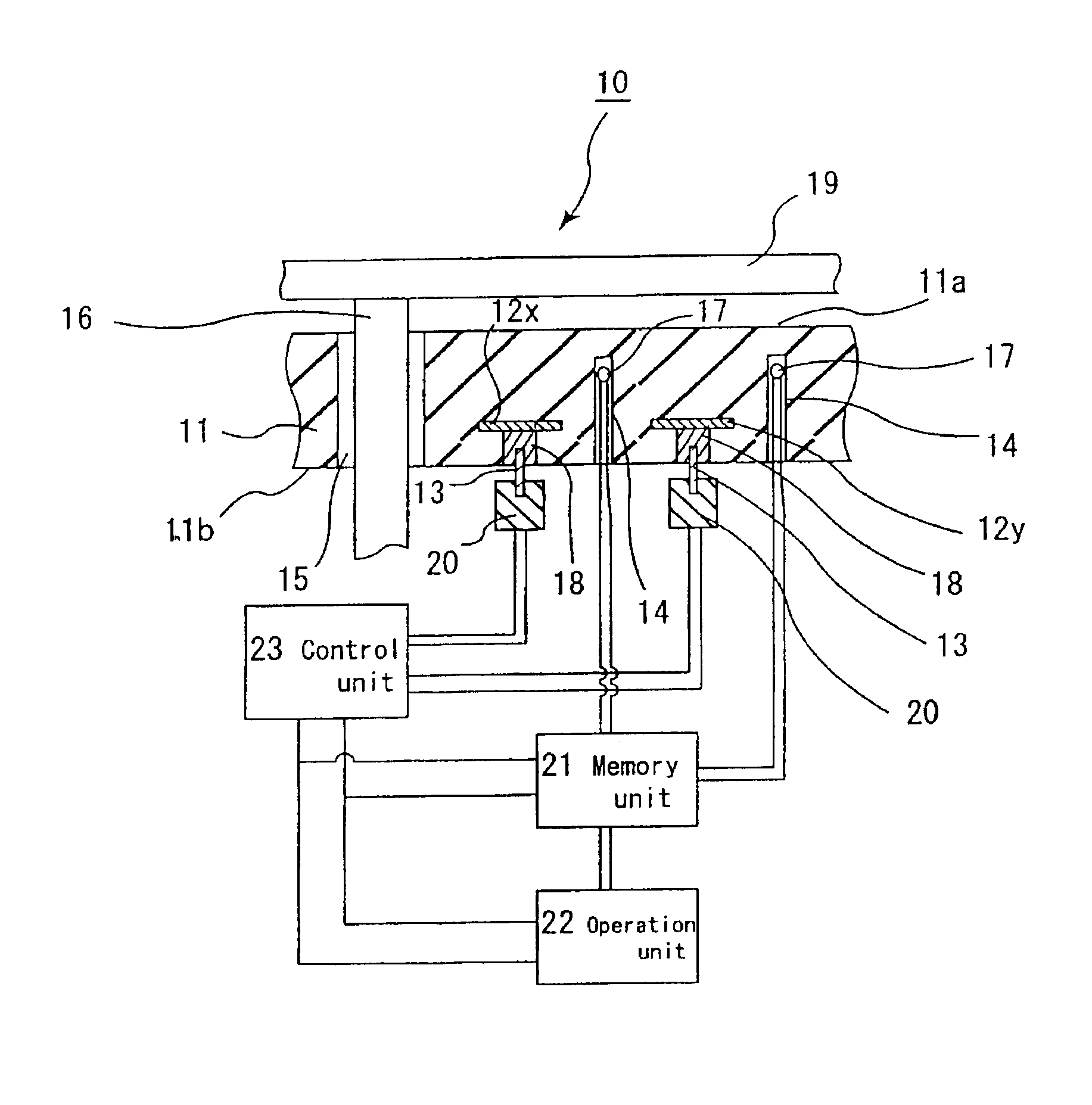
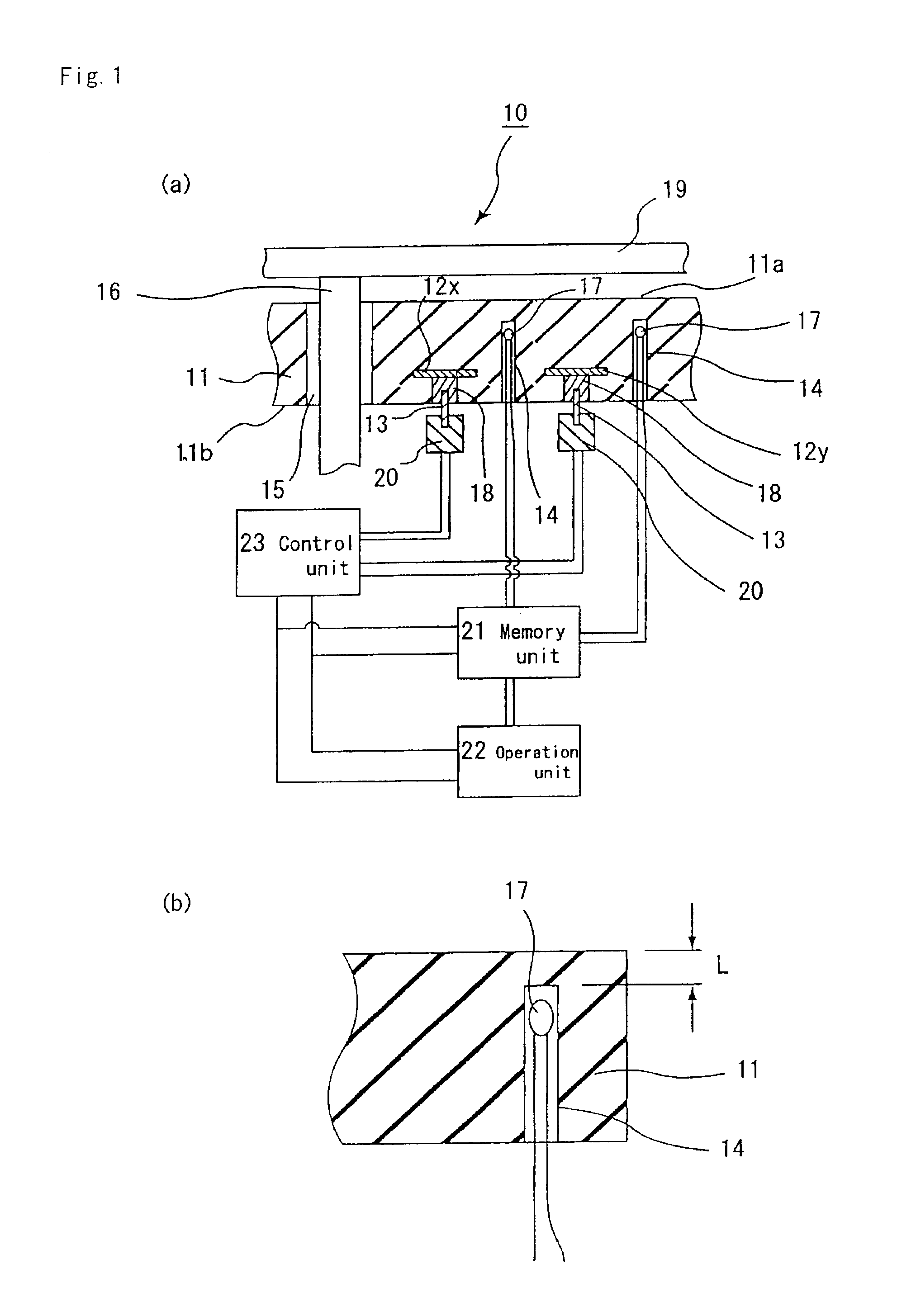
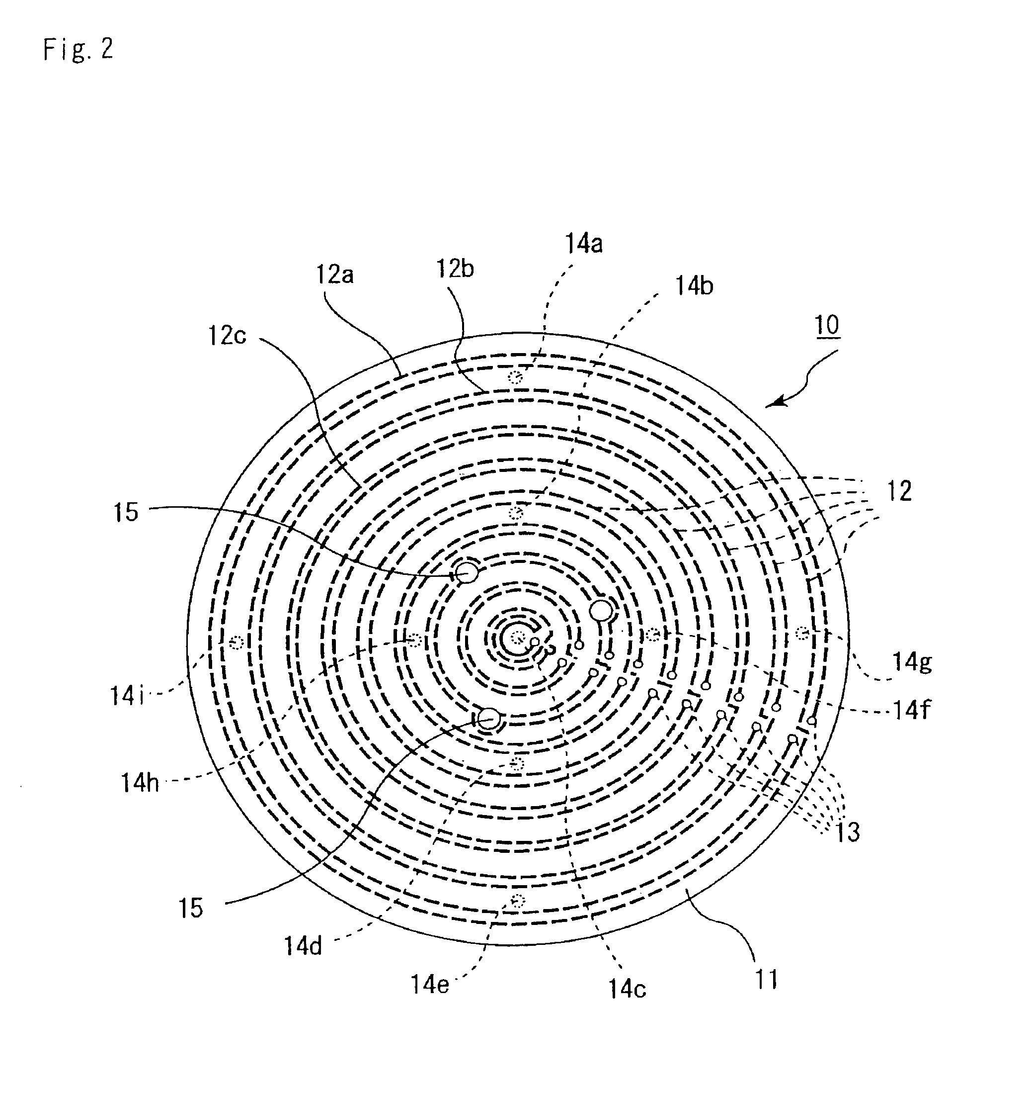
Manufacture of a Ceramic Heater having Heating Elements inside thereof. (FIGS. 1 to 2)

[0197](1) A paste obtained by mixing aluminum nitride powder (made by Tokuyama Corp., average particle diameter: 1.1 μm), 4 parts by weight of yttria (average particle diameter: 0.4 μm), 11.5 parts by weight of an acrylic binder, 0.5 part by weight of a dispersant, and 53 parts by weight of alcohols comprising 1-butanol and ethanol was formed into a green sheet having a thickness of 0.47 μm by the doctor blade process.[0198](2) Next, this green sheet was dried at 80° C. for 5 hours, and was subjected to punching to make portions for through holes 15 having diameters of 1.8 mm, 3.0 mm and 5.0 mm, respectively, into which silicon wafer lifter pins are inserted, and portions for conductor filled through holes for connection to terminal pins.[0199](3) Hundred parts by weight of tungsten carbide particles having an average particle diameter of 1 μm, 3.0 parts by weight of an acrylic binder, 3...


PUM

PropertyMeasurementUnit
thicknessaaaaaaaaaa
distanceaaaaaaaaaa
thicknessaaaaaaaaaa

Abstract

An objective of the present invention is to provide a ceramic heater making it possible to heat an object to be heated, such as a silicon wafer, evenly. The ceramic heater of the present invention is a ceramic heater having and a resistance heating element formed on the surface of the ceramic substrate or inside the ceramic substrate, wherein: said ceramic heater is equipped with: a temperature-measuring means measuring the temperature of said ceramic substrate and an object to be heated; a control unit supplying electric power to said heating element; a memory unit memorizing the temperature data measured by said temperature-measuring means; and an operation unit calculating electric power required for said heating element from said temperature, said ceramic heater being constituted such that said heating element is divided into at least 2 or more circuits and different electric power is supplied to each of the circuits of said resistance heating element.

Description

TECHNICAL FIELD[0001]The present invention relates to a ceramic heater used mainly in the semiconductor industry, for drying, sputtering and the like of the semiconductor and the like, and particularly to a ceramic heater wherein the temperature thereof can easily be controlled and the temperature evenness of its wafer-heating face is superior.BACKGROUND ART[0002]A semiconductor product is produced through the steps of forming a photosensitive resin as an etching resist on a silicon wafer and subjecting the silicon wafer to etching, and the like steps.[0003]This photosensitive resin is liquid, and is applied onto a surface of the silicon wafer, using a spin coater and the like. After the application, the resin has to be dried. Thus, the silicon wafer subjected to the application process is put on a heater and heated.[0004]Hitherto, as a heater made of metal and used for such a purpose, a heater wherein heating elements are arranged on the back surface of an aluminum plate is adopted...

Claims


Application Information

Patent Timeline
Patent Type & Authority Patents(United States)
IPC IPC(8): G05D23/19H01L21/00H05B1/02H05B3/14H05B3/20H01L21/683H05B3/00H05B3/10
CPCG05D23/1917H01L21/67103H05B1/0233H05B3/143
Inventor ITO, YASUTAKAHIRAMATSU, YASUJI
Owner IBIDEN CO LTD
Why Eureka
Try Eureka