High speed phase detector architecture

a phase detector and high-speed technology, applied in the field of communication systems, can solve the problems of phase noise and clock skew, adversely affecting the system's ability to properly recover the clock, and generating a consistent one-half data bit delay in high-speed circuits over process

Inactive Publication Date: 2005-10-18
XILINX INC
View PDF8 Cites 19 Cited by
  • Summary
  • Abstract
  • Description
  • Claims
  • Application Information

AI Technical Summary

Problems solved by technology

Generating a consistent one-half data bit delay in high speed circuits over process, voltage, and temperature and in the presence of phase noise and clock skew is problematic.
Jitter and other timing delays, however, adversely affect a system's ability to properly recover a clock in a received signal.
For instance, switching from a complimentary metal oxide semi-conductor (CMOS) process to a silicon germanium or gallium arsenide process would allow integrated circuit transceivers to operate at greater speeds, but at substantially increased manufacturing costs.
Currently, for most commercial-grade applications, including communication systems, such alternate integrated circuit fabrication processes are too cost prohibitive for wide spread use.

Method used


Image

  • High speed phase detector architecture
  • High speed phase detector architecture
  • High speed phase detector architecture

Examples


Embodiment Construction

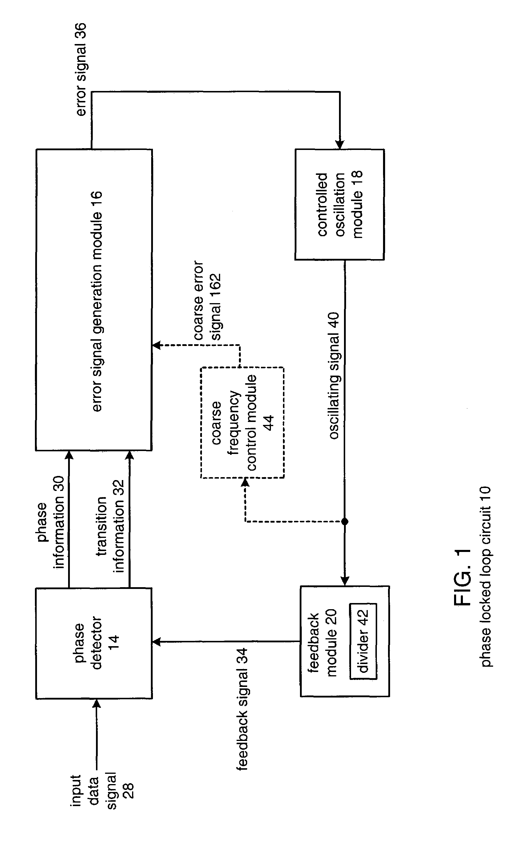
[0017]FIG. 1 illustrates a block diagram of a phase locked loop circuit 10 in accordance with the present invention. The phase locked loop circuit 10 includes a phase detector 14, an error signal generation module 16, a controlled oscillation module 18, and a feedback module 20. Phase locked loop circuit 10 may include a coarse frequency control module 44 (illustrated in dashed lines) coupled to quickly establish a desired frequency for controlled oscillation module 18. The operation of coarse frequency control module 44 will be discussed with reference to FIG. 5.

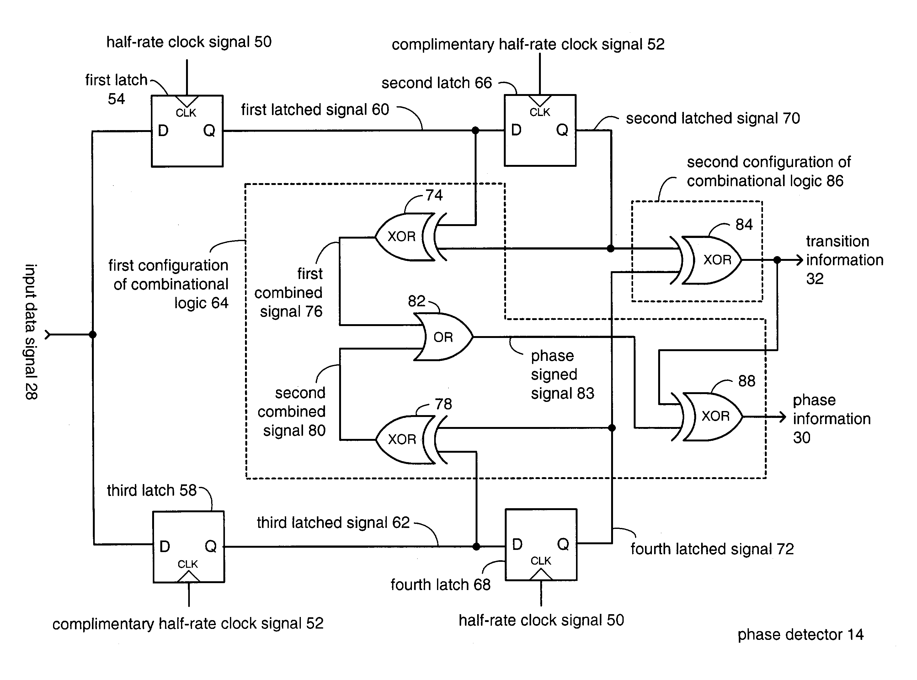
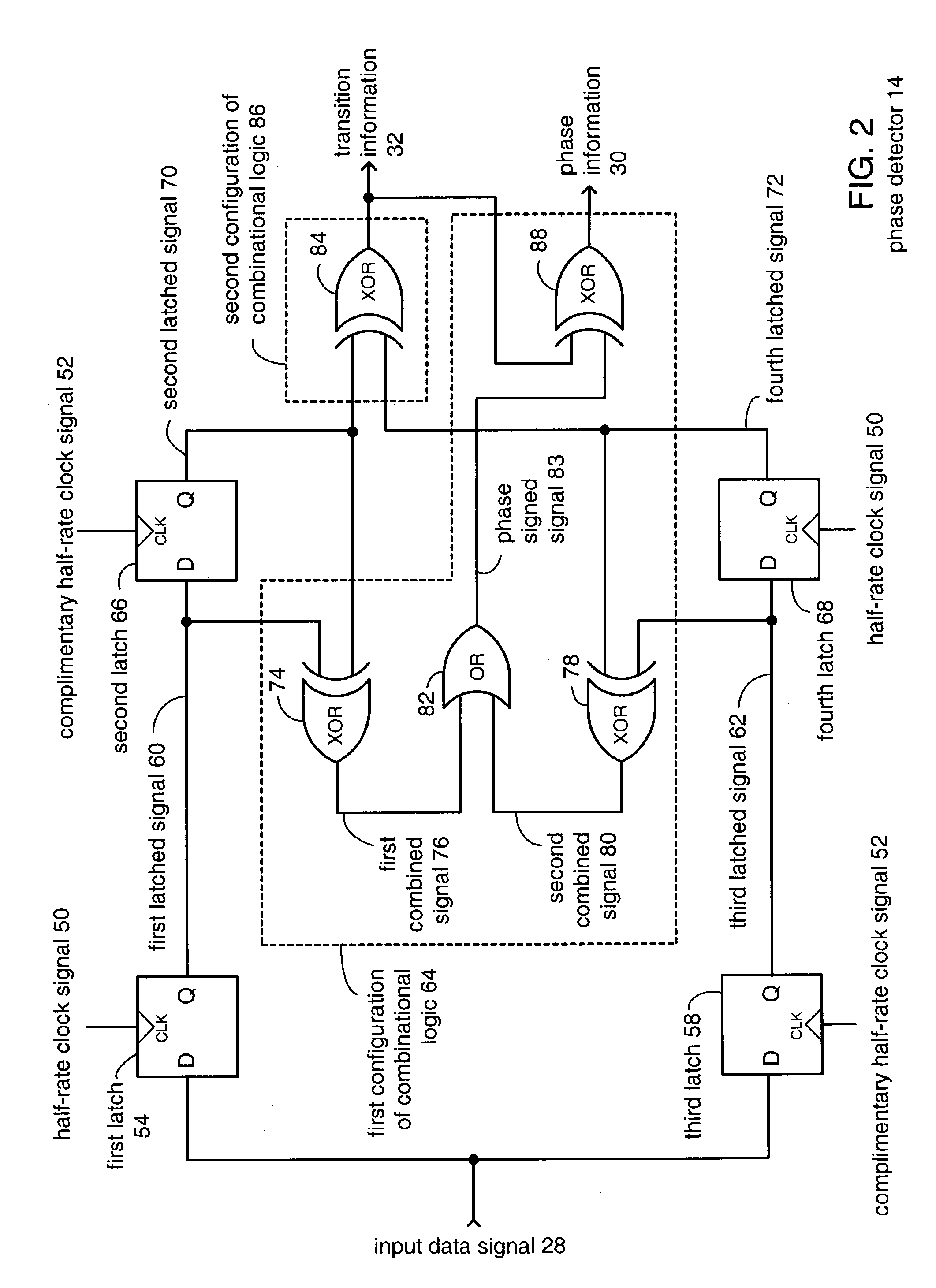
[0018]Phase detector 14 receives input data signal 28, which may be a high data rate bit stream (for example, 10 gigabits per second). Phase detector 14 produces phase information 30 and transition information 32 based on input data signal 28 and a feedback signal 34. Operation of phase detector 14 will be discussed in greater detail with reference to FIG. 2. Error signal generation module 16 produces an error signal 36 bas...


PUM


Abstract

A high speed phase detector circuit operating at a clock speed equal to one-half an input data rate (i.e. a half-rate clock) provides phase information and transition information from incoming serial data. The high speed phase detector circuit samples the incoming serial data on both the rising edge and falling edge of the half-rate clock to provide equivalent full high speed data rate sampling. The high speed phase detector circuit generates a delay between the phase information and the transition information. The phase information is produced in a first bit period and the transition information is produced in a second bit period relative to the first bit period.

Description

FIELD OF THE INVENTION[0001]This invention relates generally to communication systems and more particularly to high speed phase detector circuits used therein.DESCRIPTION OF RELATED ART[0002]Communication systems are known to transport large amounts of data between a plurality of end user devices, which, for example, includes telephones, facsimile machines, computers, television sets, cellular telephones, personal digital assistants, etc. As is also known, such communication systems may be local area networks (LANs) and / or wide area networks (WANs) that are stand-alone communication systems or interconnected to other LANs and / or WANs as part of a public switched telephone network (PSTN), packet switched data network (PSDN), integrated service digital network (ISDN), or Internet. As is further known, communication systems include a plurality of system equipment to facilitate the transporting of data. Such system equipment includes, but is not limited to, routers, switches, bridges, g...

Claims


Application Information

Patent Timeline
Patent Type & Authority Patents(United States)
IPC IPC(8): H03L7/087H03L7/08H03L7/089H03D13/00H03L7/091H03L7/10H04L7/033
CPCH03D13/003H03L7/087H03L7/0896H03L7/091H03L7/10H04L7/033H03L7/113
Inventor YOUNIS, AHMEDROKHSAZ, SHAHRIAR
Owner XILINX INC
Why Eureka
Try Eureka